3D Printing Functional Parts: Hinges, Clips, and Print-in-Place Mechanisms
Beyond Decorative: Making Parts That Actually Work
Most 3D printing content focuses on figurines, vases, and decorative items. That’s fine, but the moment I started printing functional mechanical parts — hinges that flex, clips that snap, mechanisms that move right off the build plate — everything changed. My printer stopped being a toy and became the most useful tool in my workshop.
Functional parts demand a completely different mindset than decorative prints. Tolerances matter. Material choice is critical. And small design decisions determine whether your part works for years or breaks the first time you use it.
Here’s everything I’ve learned about printing parts that actually function.

Living Hinges: Flexible Connections From a Single Print
A living hinge is a thin, flexible section that connects two rigid parts — think of the hinge on a shampoo bottle cap. In 3D printing, living hinges let you create foldable parts without any hardware. One print, no assembly.
Design Rules
- Thickness: 0.4-0.8mm for TPU, 0.6-1.0mm for PETG, 0.8-1.2mm for PLA (PLA is the worst choice for living hinges)
- Width: At least 10mm to distribute stress. Narrow living hinges concentrate force and crack quickly
- Radius: Add a fillet radius at the transition between the hinge and the rigid sections. Sharp corners = stress concentrators = cracks
- Orientation: Print the hinge so layer lines run parallel to the fold axis. Perpendicular layer lines will delaminate on the first bend
Material Choice
TPU is king for living hinges. A 95A TPU hinge can flex thousands of times without fatigue. PETG works for hinges that won’t flex frequently (maybe 50-100 cycles). PLA living hinges are a last resort — they work for a few dozen cycles before cracking, especially in cold environments.
Print Settings
Print the hinge section at 100% infill with the maximum number of walls. The hinge needs to be solid material, not a sandwich of infill and walls. Slow your print speed to 25-30mm/s through the hinge area for maximum layer bonding. Zero fan speed through thin hinge sections helps with inter-layer adhesion.
Snap-Fit Clips: The Click That Means It Worked
Snap-fit clips are the most useful functional feature in 3D printing. Battery covers, enclosure latches, panel clips, phone holders — anything that needs to lock in place without screws.
Types of Snap Fits
- Cantilever snap: The most common. A flexible arm with a hook that deflects during insertion and snaps into a groove. Used in battery covers, cable clips, and panel mounts.
- Annular snap: A ring that snaps over or into a cylinder. Think pen caps or tube connectors.
- Torsional snap: The clip twists to lock. Less common in 3D printing but useful for specific applications.
Critical Dimensions
The magic numbers for cantilever snaps:
- Beam length: Longer = more flexible = easier insertion. Start at 15-20mm for PETG, 20-25mm for PLA
- Hook overhang: 0.5-1.0mm for easy insertion, 1.0-2.0mm for secure hold
- Beam thickness: 1.5-2.5mm. Too thin and it breaks; too thick and it won’t flex
- Catch angle: 30-45° entry angle (easy to push in), 80-90° retaining angle (hard to pull out)
Design for Layer Direction
This is where most people fail. A snap clip printed with layer lines perpendicular to the flex direction will snap off immediately. The beam must be oriented so it flexes along the layer lines, not across them. If this means printing the entire enclosure in a non-obvious orientation, so be it — the clip direction drives the print orientation.
Print-in-Place Mechanisms: Magic Off the Build Plate
Print-in-place (PIP) mechanisms are parts that come off the printer already assembled and functional — gears that mesh, bearings that spin, chains that flex. No assembly required. They’re impressive to watch and genuinely useful when designed correctly.
The Critical Parameter: Clearance
The gap between moving parts is everything. Too tight and the parts fuse together. Too loose and there’s excessive play.
- PLA: 0.3-0.4mm clearance between moving parts
- PETG: 0.35-0.45mm clearance (PETG is slightly “stickier”)
- TPU: Generally not suitable for PIP — too flexible and adhesive
These numbers are for a 0.4mm nozzle at 0.2mm layer height. If you’re using a different setup, you’ll need to calibrate with test prints.
Calibration Test
Before printing a complex PIP mechanism, print a simple clearance test. Design two concentric cylinders with varying gaps (0.2mm, 0.3mm, 0.4mm, 0.5mm). Print them flat on the bed. After printing, try to separate them. The smallest gap that allows free movement is your printer’s PIP clearance for that material and those settings.
My Ender-3 V3 does 0.3mm clearance reliably with PLA. My Bambu Lab X1 Carbon manages 0.25mm. Your results will vary — always test first.
Design Tips for PIP
- First layer matters: The first layer squishes more than subsequent layers, potentially fusing parts at the bottom. Add extra clearance (0.1mm more) for the first 2-3 layers, or use a sacrificial raft
- Elephant foot kills PIP: Tune your first layer to eliminate elephant foot before attempting PIP parts. Even 0.1mm of extra squish can fuse your mechanism
- Chamfer mating surfaces: Add 0.5mm chamfers where parts meet to help with break-away after printing
- Support-free geometry: Design PIP parts so no internal surface exceeds a 45° overhang. Internal supports are impossible to remove from assembled mechanisms
Tolerance Guidelines for Functional Assemblies
When you’re printing parts that need to fit together — whether it’s a two-piece enclosure, a shaft in a bearing, or a snap-fit lid — tolerances determine success or failure.
Press Fit (Interference Fit)
Hole 0.1-0.2mm smaller than the shaft. The parts press together and friction holds them. Works for bearings, bushings, and permanent connections. PLA and PETG both work well.
Sliding Fit
0.2-0.3mm clearance. Parts slide together but don’t rattle. Ideal for drawers, telescoping tubes, and linear guides.
Loose Fit
0.3-0.5mm clearance. Parts move freely. Used for rotating joints, hinges with pins, and any connection where free movement is needed.
Threaded Connections
For printed threads, add 0.2-0.3mm to both the major and minor diameters beyond standard thread specs. Printed threads need more clearance than machined ones because of layer stepping on angled surfaces. M6 and larger threads print reliably; below M4, use heat-set inserts instead.
Best Materials for Functional Parts
| Application | Best Material | Why |
|---|---|---|
| Living hinges | TPU 95A | Flex fatigue resistance |
| Snap clips | PETG | Good flex + strength balance |
| PIP mechanisms | PLA | Low warp, precise clearances |
| Load-bearing brackets | CF-Nylon | Maximum stiffness-to-weight |
| Outdoor parts | ASA | UV + weather resistance |
| High-temp parts | PETG or PC | Heat resistance above PLA’s limit |
Print Settings for Functional Parts
Walls Are Everything
For functional parts, increase wall count from the default 2-3 to 4-5. Walls carry the structural load in most FDM parts. A part with 5 walls and 10% infill is often stronger than one with 2 walls and 50% infill.
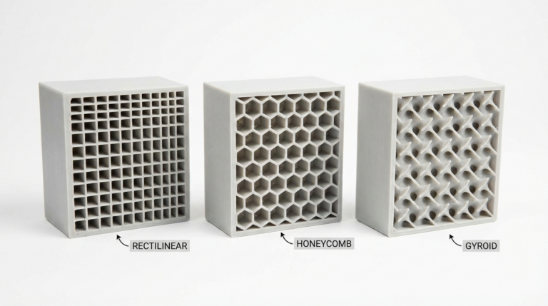
Infill Pattern Matters
For parts that need multi-directional strength, use cubic or gyroid infill. For parts loaded primarily in one direction, grid or triangle infill aligned with the load is stronger. For PIP parts, keep infill at 15-20% to reduce warping that can fuse clearances.
Layer Adhesion is Structural
Increase print temperature by 5-10°C above your visual-quality settings. Reduce fan speed by 20-30%. Use thicker layers (0.24-0.28mm) for better inter-layer bonding. The finish won’t be as smooth, but the part will be dramatically stronger.
Testing Before Trusting
Every functional part should go through a test cycle before you rely on it:
- Fit check: Does it assemble correctly? Tolerances right?
- Flex test: For hinges and clips, cycle them 20-30 times by hand. Any signs of whitening or cracking?
- Load test: Gradually apply the expected load. If it’s a hook rated for 2kg, test it with 3kg.
- Environment test: If the part lives outdoors or in heat, expose it to those conditions for 24 hours before trusting it in service.
3D printed functional parts are incredibly capable when designed and printed correctly. The gap between a decorative model and a working mechanism isn’t just settings — it’s a mindset shift toward engineering thinking. Start with simple clips and hinges, build up to print-in-place mechanisms, and before long you’ll be designing custom solutions for problems you didn’t even know you could solve with a printer.