3D Print Walls Not Touching Infill? How to Fix Gaps for Stronger Parts
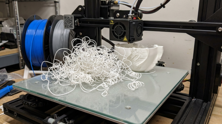
You slice a model, start the print, and everything looks fine until you break the part and discover the walls and infill aren’t properly bonded. Or maybe you can see it happening in real-time — visible gaps where the outer walls should meet the internal infill pattern. This is one of those problems that doesn’t always look obvious from the outside but absolutely kills part strength.
Gaps between walls and infill mean your 3D print is structurally compromised. The infill can’t transfer loads to the walls, and the walls can’t rely on the infill for support. Let’s fix it.
What Causes Gaps Between Walls and Infill?
The root cause is almost always a mismatch between how your slicer generates wall paths and infill paths. These two sets of toolpaths need to overlap slightly for a strong bond, and when they don’t, you get gaps. Here’s why it happens:
1. Infill Overlap Percentage Is Too Low
This is the single most common cause. Your slicer has a setting called “Infill Overlap” (Cura) or “Infill/Perimeter Overlap” (PrusaSlicer) that controls how much the infill lines overlap with the inner wall.
Default values are often too conservative:
- Cura default: 30% (of line width)
- PrusaSlicer default: 25%
The fix: Increase infill overlap to 40-50%. In some cases, you may need to go up to 60% for very strong bonds. The tradeoff is a slightly less clean inner surface, but since this is interior geometry, it doesn’t matter aesthetically.
In Cura: Search for “Infill Overlap Percentage” and increase it.
In PrusaSlicer: Print Settings → Advanced → “Infill/perimeters overlap”
In OrcaSlicer: Quality → “Infill/wall overlap”
2. Under-Extrusion
If your printer isn’t pushing enough plastic, everything comes out slightly thinner than expected — including both walls and infill. Even a 5% extrusion deficit can create visible gaps at the wall-infill junction because the lines simply aren’t wide enough to touch.
How to verify:
- Print a single-wall calibration cube
- Measure the wall thickness with calipers
- Compare to your slicer’s line width setting (typically 0.4mm for a 0.4mm nozzle)
- If walls measure under 0.38mm, you’re under-extruding
Common causes of under-extrusion:
- E-steps not calibrated (most common)
- Extruder tension too low — filament slipping on the drive gear
- Partial nozzle clog restricting flow
- Printing too fast for the hotend’s melt capacity
- Worn nozzle with a larger-than-spec bore
3. Print Speed Mismatch
Many slicers let you set different speeds for walls and infill. If infill prints much faster than walls, the extruder may not keep up with the flow demand when transitioning from slow walls to fast infill. This creates a brief under-extrusion at the transition point — right where wall meets infill.
The fix:
- Keep the speed ratio between walls and infill under 2:1
- If walls print at 40 mm/s, keep infill under 80 mm/s
- Or enable flow rate compensation if your firmware supports it
4. Thin Wall Detection Issues
When your model has walls that aren’t an exact multiple of your nozzle width, the slicer may leave thin gaps that it can’t fill with standard-width lines. This isn’t technically a wall-infill gap, but it looks identical.
The fix:
- Enable “Fill Gaps Between Walls” in Cura
- Enable “Gap fill” in PrusaSlicer (usually on by default)
- Adjust wall count or line width so walls fill the available space without leaving sub-line-width gaps
- Use the Arachne (variable width) wall generator in Cura — it dynamically adjusts line width to eliminate gaps
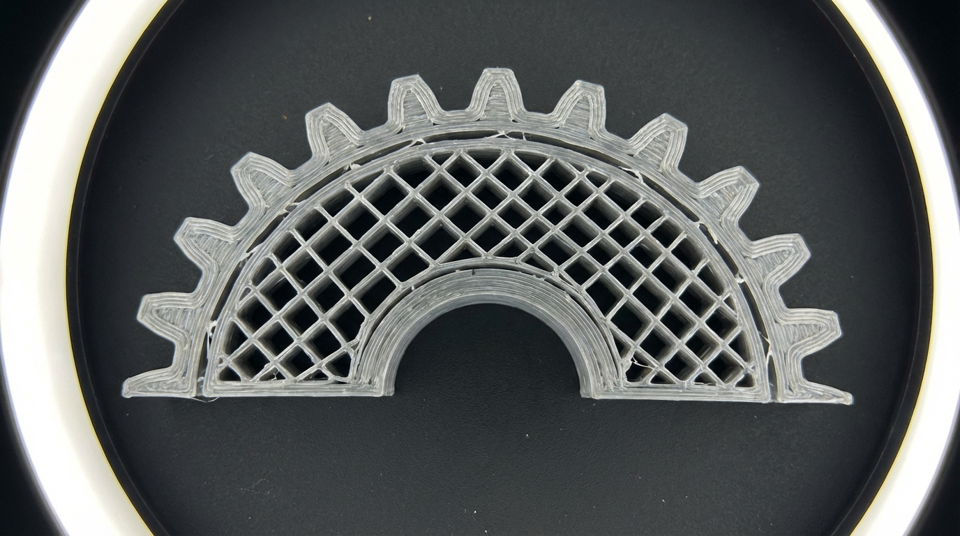
5. Infill Pattern Choice
Some infill patterns connect better to walls than others. Patterns that run parallel to walls at certain points can leave longer unsupported gaps.
Best patterns for wall-infill bonding:
- Cubic — Good multi-directional contact with walls
- Gyroid — Continuous curved paths with frequent wall contact
- Grid — Simple but effective, contacts walls at 90° regularly
Patterns that may show more gaps:
- Lines — Long parallel runs can miss wall contact points
- Concentric — Can leave gaps in non-circular geometries
6. Nozzle Wear
A worn brass nozzle has a larger bore than its rating. A “0.4mm” nozzle that’s actually 0.45mm will produce slightly thinner lines than the slicer expects (because flow rate is calculated for 0.4mm). This subtle under-extrusion shows up most at junction points.
The fix: Replace the nozzle. If you print abrasive filaments (CF, GF, glow-in-the-dark), switch to a hardened steel or ruby-tipped nozzle that resists wear.
The Systematic Fix: Step by Step
If you’re seeing wall-infill gaps, work through these fixes in order:
- Increase infill overlap to 45% — This alone fixes 70% of cases
- Calibrate E-steps — Make sure your extruder is delivering the right amount of plastic
- Check flow rate — Print a flow calibration model and adjust flow/extrusion multiplier
- Slow down infill — Match it closer to your wall speed
- Enable gap fill — Let the slicer fill thin gaps with additional lines
- Switch to Arachne wall generator — Variable-width walls eliminate gaps by design
- Check nozzle condition — Replace if worn or partially clogged
Slicer-Specific Settings
Cura Settings
- Infill Overlap Percentage: 40-50%
- Fill Gaps Between Walls: Everywhere
- Wall Ordering: Inside to Outside (helps infill bond to inner wall)
- Wall Generator: Arachne
- Connect Infill Lines: Enabled
- Infill Before Walls: Disabled (print walls first for cleaner exterior)
PrusaSlicer / OrcaSlicer Settings
- Infill/Perimeters Overlap: 30-40% (PrusaSlicer uses smaller numbers for equivalent results)
- Gap fill: Enabled
- External perimeters first: Disabled for strength, enabled for aesthetics
- Infill every N layers: 1 (don’t skip layers for infill — it weakens the bond)
When Gaps Still Won’t Go Away
If you’ve tried everything above and still see gaps:
- Increase nozzle temperature by 5-10°C — Hotter plastic flows better and bonds to adjacent lines more easily
- Increase line width to 110-120% of nozzle diameter — Wider lines squish more, forcing better contact
- Add more walls — More wall lines mean the inner wall that contacts infill is under more pressure from the outer walls, improving bonding
- Reduce infill line width — Narrower infill lines get pushed more into the wall contact zone by the overlap setting
Does It Actually Matter?
For decorative prints? Not really. Gaps between walls and infill are an internal issue — you won’t see them on the surface.
For functional parts? Absolutely yes. Wall-infill gaps reduce:
- Tensile strength by 20-40% in some orientations
- Impact resistance (the wall can separate from infill on impact)
- Water-tightness (if you’re trying to print containers or enclosures)
If you’re printing anything load-bearing — brackets, mounts, enclosures, functional prototypes — fixing wall-infill gaps should be a priority. It’s one of the biggest hidden weaknesses in FDM prints, and the fixes are all in software. No hardware changes required.
Quick Reference Checklist
- ✅ Infill overlap: 40-50%
- ✅ E-steps calibrated
- ✅ Flow rate calibrated (±2% of ideal)
- ✅ Wall-infill speed ratio under 2:1
- ✅ Gap fill enabled
- ✅ Arachne wall generator (Cura) or equivalent
- ✅ Nozzle in good condition
- ✅ Print temp adequate for material
Get these right, and your walls and infill will bond like they’re supposed to. Your parts will be stronger, more reliable, and actually perform the way the infill pattern promises.