3D Printer Bed Tramming and Mesh Compensation: The Complete Guide to a Perfect First Layer
What Is Bed Tramming and Why Does It Matter?
Here’s a dirty secret about 3D printing: “bed leveling” is a misnomer. What you’re actually doing is tramming — adjusting the build plate so it sits perfectly parallel to the printer’s motion system. The bed doesn’t need to be level relative to the earth (your printer doesn’t care about gravity). It needs to be level relative to the gantry that carries the print head.
Poor tramming is behind a staggering number of failed first layers. One corner too high, and the nozzle drags through the filament, creating scars. One corner too low, and the filament doesn’t squish enough to stick. Get tramming right, and you eliminate an entire category of print failures.
Manual Tramming: The Paper Method Done Right
The classic paper-under-the-nozzle method works better than most people realize — if you do it correctly. The problem isn’t the method; it’s that most tutorials skip the critical details.
What You Need
- A standard sheet of printer paper (approximately 0.1 mm thick)
- Clean nozzle — purge any filament before starting
- Bed at printing temperature (thermal expansion changes the geometry)
- Patience for at least two full passes
Step-by-Step Manual Tramming
- Heat the bed to your printing temperature. Aluminum beds expand when heated. Tramming at room temperature and printing at 60°C means your “level” bed is now warped by thermal expansion. Always tram hot.
- Home all axes. This establishes the printer’s reference point.
- Disable steppers (most printers have a menu option, or send
M84via terminal). This lets you move the print head manually. - Move the head to the first corner. Start with the front-left. Slide the paper under the nozzle — you want slight friction, not a hard stop and not free sliding. Think of it as the resistance of pulling a post-it note off a desk.
- Adjust that corner’s knob. Clockwise typically raises the bed (check your printer — some are reversed). Adjust until you feel consistent light drag on the paper.
- Move to the opposite corner (back-right). Adjust to match. Then do front-right and back-left.
- Return to the first corner and check again. This is the step everyone skips. Adjusting one corner affects the others because the bed pivots. You need at least two full circuits to converge.
- Check the center. If the center feels tighter or looser than the corners, your bed may be warped — that’s where mesh compensation comes in.
Common Manual Tramming Mistakes
- Tramming cold: Thermal expansion makes your cold tramming worthless at print temps
- Only one pass: Each adjustment shifts the others. Minimum two complete passes.
- Using thick paper: Standard 80 gsm paper is ideal. Cardstock or receipt paper gives wrong gap.
- Ignoring the center: A warped bed can be perfect at all four corners and 0.2 mm off in the middle
- Dirty nozzle: Residual filament on the nozzle tip adds unpredictable thickness to your gap
Probe-Based Tramming Assistants
If you have a BLTouch, CR Touch, or inductive probe, your printer can measure the bed’s tilt for you. This doesn’t replace manual tramming — it measures how far off you are so you can adjust the knobs with precision instead of feel.
Klipper’s SCREWS_TILT_CALCULATE
Klipper users have access to one of the best tramming tools available: SCREWS_TILT_CALCULATE. This command probes the bed above each leveling screw and tells you exactly how far to turn each knob.
The output looks something like this:
01:20 means 1 full turn and 20 minutes clockwise
00:45 means 45 minutes counter-clockwise (CCW)
It uses clock notation — brilliant for translating probe measurements into physical knob turns. Configure it by adding your screw positions to printer.cfg:
[screws_tilt_adjust]
screw1: 30,30
screw1_name: front left
screw2: 200,30
screw2_name: front right
screw3: 200,200
screw3_name: rear right
screw4: 30,200
screw4_name: rear left
speed: 100
horizontal_move_z: 10
screw_thread: CW-M4
Marlin’s Tramming Wizard
Recent Marlin firmware versions include a tramming wizard accessible through the LCD menu. It probes corners sequentially and shows deviation values. Less intuitive than Klipper’s clock notation but gets the job done. Look for it under Motion → Bed Tramming or similar menu paths depending on your firmware build.
Understanding Mesh Bed Compensation
Even a perfectly trammed bed has imperfections. Manufacturing tolerances, thermal warping, and the simple reality that no aluminum plate is perfectly flat mean your bed has hills and valleys. Mesh bed compensation maps these imperfections and adjusts the Z height during printing to compensate.
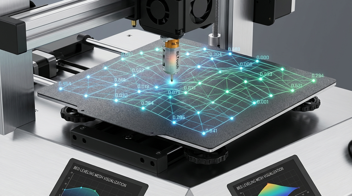
How Mesh Compensation Works
The printer probes the bed at a grid of points — typically 9 (3×3), 25 (5×5), or more. At each point, it records the Z offset from the expected plane. During printing, the firmware uses bilinear interpolation between these points to adjust Z height in real time, raising or lowering the nozzle by fractions of a millimeter to maintain consistent first-layer squish across the entire bed.
Choosing Your Probe Grid
- 3×3 (9 points): Fast, adequate for flat beds with minor imperfections. Probing takes about 30 seconds.
- 5×5 (25 points): Good balance of accuracy and speed. Catches most bed warps. About 90 seconds.
- 7×7 (49 points): High resolution, catches localized dips. Good for warped beds. About 3 minutes.
- 10×10 (100 points): Overkill for most setups but useful if your bed has complex warps. 5+ minutes.
For most printers, a 5×5 grid strikes the best balance. Only increase density if you have a known warped bed or see first-layer inconsistencies even with compensation active.
Klipper Mesh Setup
In Klipper’s printer.cfg:
[bed_mesh]
speed: 120
horizontal_move_z: 5
mesh_min: 10,10
mesh_max: 220,220
probe_count: 5,5
algorithm: bicubic
fade_start: 1
fade_end: 10
Key parameters:
- mesh_min/mesh_max: Define the probed area. Keep it within your probe’s physical reach.
- algorithm: Use
bicubicfor 4×4 grids and larger. Uselagrangeonly for 3×3 or smaller. - fade_start/fade_end: Gradually reduces compensation over the first few layers, so upper layers aren’t affected by bed topology. Start at 1 mm, end at 10 mm.
Marlin Mesh Setup
Marlin supports three mesh approaches:
- Auto Bed Leveling (ABL): Uses a probe to automatically generate the mesh. Enable
AUTO_BED_LEVELING_BILINEARin Configuration.h. - Unified Bed Leveling (UBL): The most advanced option. Stores mesh persistently, allows manual point editing, and supports tilt compensation. Enable
AUTO_BED_LEVELING_UBL. - Manual Mesh Leveling: For printers without probes. The firmware walks you through each point, and you adjust Z manually. Enable
MESH_BED_LEVELING.
The Complete Tramming + Mesh Workflow
Here’s the workflow that produces the best results:
- Rough manual tram with the paper method. Get all four corners within 0.1 mm.
- Run probe-assisted tramming (SCREWS_TILT_CALCULATE or equivalent). Adjust knobs based on measurements.
- Repeat step 2 until all corners show minimal deviation (under 0.02 mm).
- Run bed mesh probe. Save the mesh profile.
- Calibrate Z offset. This sets the absolute distance between the probe trigger point and the nozzle tip.
- Print a first-layer test (large single-layer square). Adjust Z offset live until the first layer looks perfect across the entire bed.
Important: Always tram before meshing. Mesh compensation works best when correcting small imperfections (±0.1 mm), not large tilts. If your bed is 0.5 mm out of tram, the mesh has to do heavy lifting that reduces print quality.
Saving and Loading Mesh Profiles
Most firmware allows you to save mesh profiles so you don’t have to probe every print. In Klipper, mesh profiles are saved with BED_MESH_PROFILE SAVE=name and loaded in your start G-code with BED_MESH_PROFILE LOAD=name. In Marlin, use M500 to save to EEPROM.
However, there’s a nuance: bed shape changes with temperature. A mesh probed with the bed at 60°C may not be accurate at 100°C. If you print multiple materials at different bed temperatures, consider maintaining separate mesh profiles for each temperature.
Troubleshooting Mesh Issues
Mesh Looks Wildly Uneven
If your mesh visualization shows extreme peaks and valleys (more than ±0.3 mm), something is wrong mechanically. Check for:
- Loose bed mounting screws
- Warped build plate (common with thin aluminum beds)
- Probe wiring issues causing false triggers
- Magnetic build plate not seated properly
First Layer Still Inconsistent After Meshing
If mesh compensation is active but your first layer still varies, check these:
- Z offset not dialed in: Mesh corrects relative differences but can’t fix an absolute offset that’s wrong
- Mesh not loading: Verify your start G-code actually loads the mesh before printing
- Fade settings too aggressive: If fade_end is too low (like 2–3 mm), compensation drops off before the first layer is established
- Probe temperature drift: Some probes (especially inductive types) change trigger distance as they heat up
Mesh Takes Too Long
If probing takes forever, reduce the grid density or increase probe travel speed. A 3×3 grid at 150 mm/s travel completes in under 20 seconds. You can also use Klipper’s BED_MESH_CALIBRATE ADAPTIVE=1 to only probe the area where your actual print will be — this dramatically reduces probing time for small prints on large beds.
Best Practices for Long-Term Bed Management
- Re-tram every 20–30 prints or whenever you remove/reinstall the bed
- Re-mesh when switching bed surfaces (glass to PEI, magnetic to BuildTak)
- Store mesh profiles for different bed surfaces and temperatures
- Keep bed mounting hardware tight — loose wheels or springs slowly detram the bed
- Periodically check for bed warping with a straightedge against the surface
Wrapping Up
Bed tramming and mesh compensation are the foundation of reliable 3D printing. Get these right, and you’ll spend less time fighting first-layer adhesion and more time printing. The investment is maybe 15 minutes of setup time — once you’ve nailed your tramming and saved a mesh profile, it’s smooth sailing until something physically changes on your printer. And when it does, you’ll know exactly how to fix it.