High Temp Filament for Automotive Engine Bay Parts: 2026 Application Guide
Why “Heat Resistant” Filament Marketing Lies for Automotive Use
When a filament spool is marketed as “heat resistant” for automotive use, the temperature claim on the box is almost always the glass transition temperature (Tg), not the continuous service temperature. These two numbers are very different in practice. PLA-HT advertises 95°C Tg but starts deforming under any sustained load at 60°C. PETG-HT lists 80°C Tg but parts deform at 55-60°C under load. ABS lists 105°C Tg but the continuous service temperature for load-bearing parts is closer to 80°C. For an engine bay component, where ambient temperatures during summer driving can reach 80-100°C at the firewall and 120-140°C near the exhaust manifold, none of those filaments are appropriate.
This guide walks through which filaments actually work for which engine bay locations in 2026, what the realistic service temperature is for each, and what specific failure modes show up when each material is pushed past its limit. The numbers come from automotive 3D printing communities running real parts on real vehicles, not from manufacturer datasheets.
Mapping Engine Bay Temperatures Honestly
Engine bay temperatures vary dramatically by location, vehicle type, and operating conditions. A turbocharged engine in stop-and-go summer traffic produces an entirely different temperature profile than a naturally aspirated daily driver in spring weather. Approximate zone temperatures for a typical modern car under sustained hard driving in 80°F ambient:
Battery box / fuse box area: 50-70°C. Most filaments work here. PETG, ABS, and ASA are all fine for components like battery hold-downs, fuse box brackets, and cable routing clips.
Firewall area / cabin air intake: 70-90°C. ABS holds up but creeps under load. ASA is better. Nylon (PA6 or PA12) is the realistic minimum for any structural part.
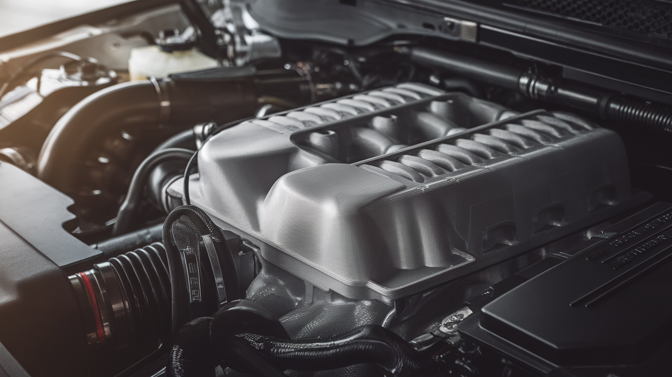
Engine cover / intake plenum area: 90-110°C. Polycarbonate (PC), polycarbonate-CF, or PA-CF are the practical minimums. ABS will deform within weeks.
Turbo manifold / exhaust adjacent: 120-200°C+. PEI (Ultem), PEEK, and PEKK are the only filaments that survive long-term. Even PA-CF struggles here under sustained load.
Direct exhaust contact / inside manifold: 250°C+. No FDM 3D printed material survives here. Use metal parts, not 3D printed plastic.
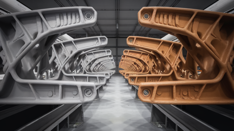
PA-CF for the Mid-Engine-Bay Workhorse
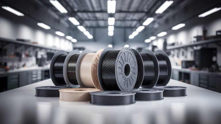
Polyamide carbon fiber (PA-CF) has become the default mid-temperature filament for automotive applications in 2026. Service temperature for PA-CF is honest at 100-120°C continuous, with short-term excursions to 140°C tolerable. The carbon fiber content provides dimensional stability that pure nylon lacks — pure PA6 will absorb moisture and grow several millimeters over a few weeks in summer humidity, but PA-CF holds dimensions within 0.2 mm over the same period.
PA-CF prints in the 280-300°C range on the nozzle with a heated chamber. A hardened steel or tungsten carbide nozzle is mandatory because the carbon fiber wears brass nozzles aggressively — a 100-meter spool of PA-CF will ruin a brass nozzle. The print must be annealed after printing for full mechanical performance: 120°C for 2-4 hours in a convection oven (a kitchen oven works) brings the part to dimensional stability and increases strength roughly 30 percent.
Typical PA-CF parts in the engine bay: intake plenum brackets, sensor housings, cable routing trays where heat is a factor, throttle body adapters, and prototyping for parts that will eventually be machined. PA-CF can prototype to within a few millimeters of final fit and run for testing.
PC-CF for Dimensional Precision Under Heat
Polycarbonate-CF prints slightly hotter than PA-CF (290-310°C nozzle) and tolerates slightly less continuous heat (100-115°C reliable, with creep under sustained load above 105°C). Where PC-CF wins is dimensional stability — no moisture absorption, much less creep under sustained load than PA-CF, and very low coefficient of thermal expansion. For parts where dimensional accuracy under heat matters more than absolute heat resistance, PC-CF is the right choice.
Typical PC-CF applications: sensor mounting brackets where alignment to within a millimeter matters, optical sensor housings, fluid reservoir caps where the seal depends on consistent dimensions, brackets that must thread into existing chassis hardware. PC-CF does not absorb moisture from humidity the way PA-CF does, which is the dominant failure mode for PA-CF parts that need to maintain tight tolerances.
PEI (Ultem 9085 or 1010) for High-Heat Applications
For parts that see sustained 130-180°C, PEI is the practical filament in 2026. Ultem 9085 (the higher-grade variant) is FAA-certified for aviation interior parts, which says something about its reliability under temperature. Ultem 1010 (more common in consumer FDM) handles up to 200°C continuous with significant load. Both print in the 360-380°C nozzle range with a heated chamber at 80-100°C. The hardware requirements are not trivial: you need a printer with an all-metal hotend rated to 400°C, a chamber heater, and an active enclosure.
The realistic 2026 printers that can handle PEI: Intamsys FUNMAT HT, Roboze Argo, Apium HPP series, and the Voron 2.4 V3 with the 400°C upgrade kit. None of these are sub-$5,000 machines. For most hobbyists doing automotive prints, PEI is in the “send out to a service bureau” category rather than the “print at home” category.
Typical PEI parts in the engine bay: exhaust-adjacent sensor housings, brackets near the turbocharger, oil filler caps for race cars (not road cars — failure mode is bad), and structural parts that need both temperature and chemical resistance.
ASA for the Exterior Plastic Replacement Use Case
ASA is not really an engine bay filament — it tops out around 90°C continuous — but it is the right filament for exterior automotive parts that see UV exposure: hood scoops, mirror caps, trim pieces, license plate frames, and grille inserts. ASA holds UV stability for years where ABS chalks and yellows within months. For weather-exposed parts that do not see direct engine heat, ASA is the practical choice.
ASA prints at 240-260°C with a heated bed at 100-110°C and chamber temperatures of 35-50°C. The chamber requirement is similar to ABS, but the smell during printing is much less aggressive than ABS — ASA generates less styrene odor in normal printing.
Hardware Mounting and Vibration Considerations
Engine bay parts experience constant vibration in addition to heat. The mounting strategy matters as much as the filament choice. For 3D printed brackets, design in a rubber isolation grommet at the mounting point — direct metal-to-plastic contact at a fastener causes vibration loosening over time, regardless of how strong the filament is. M5 or M6 threaded inserts (brass heat-set inserts) installed after printing give you serviceable bolted joints. Tapping threads directly into 3D printed plastic works for prototyping but fails under sustained vibration within weeks.
Wall thickness and infill recommendations differ from typical 3D prints: 4-5 perimeters for any structural part, 30-50 percent gyroid infill, and 100 percent infill for any part that takes thread directly. The added material weight is irrelevant on automotive parts compared to the failure cost.
Annealing as the Required Post-Process
Most engineering filaments for automotive use require annealing after printing to reach rated mechanical performance. Annealing relieves internal stress, drives off residual moisture, and in semi-crystalline polymers like PA increases crystallinity. For PA-CF, anneal at 120°C for 2-4 hours in a convection oven. For PC-CF, 130°C for 2-3 hours. For PEI, 200°C for 6+ hours in a precise oven (a kitchen oven cannot hold these temperatures reliably).
Annealing causes dimensional shift — parts typically shrink 0.5-1.5 percent in X/Y and grow slightly in Z. Design parts with this anticipated dimensional change in mind, or print test parts to characterize your specific filament and annealing process. Skipping annealing on PA-CF parts that will see sustained heat is the single most common reason hobbyist automotive prints fail prematurely.
Real-World Examples of Successful Engine Bay Prints
Cold air intake brackets in PA-CF have run for two-plus years in turbocharged daily drivers without any degradation. Battery hold-down brackets in PETG-CF (carbon-fiber-reinforced PETG, not pure PETG) survive in the battery box area indefinitely. Sensor mounting brackets in PC-CF maintain alignment within 0.5mm over a full Texas summer of driving. The pattern across successful builds: pick the filament for the zone temperature, anneal where appropriate, install with rubber isolation grommets, and inspect annually.
Less successful examples are also instructive. PETG intake brackets in a turbo bay deformed within a single summer because intake-side temperatures spent significant time above the PETG service temperature. ABS oil-catch-can brackets cracked after thermal cycling on a daily driver because the bracket was loaded by an oil line whose thermal expansion exceeded the ABS creep tolerance. In both cases, the failure was material selection, not 3D printing as a method.
Chemical Resistance Matters Almost as Much as Temperature
Filaments behave differently when exposed to engine bay chemicals. Gasoline, brake fluid, coolant, and motor oil can each soften, swell, or dissolve plastics that handle temperature fine. PA-CF is generally resistant to oils and fuels but absorbs water from coolant overspray. PC-CF is excellent against fuels but vulnerable to alcohols (some E85 blends and brake fluids). PETG resists oils well but dissolves in acetone (windshield-washer fluid in some climates). PEI is essentially inert against engine bay chemicals — another reason it is the go-to for race-car high-temperature work.
For brackets that may see fluid contact, pick a filament with both adequate temperature rating and known resistance to whatever might splash on it. Online filament chemical compatibility charts from manufacturers like Polymaker, Bambu, and Prusament are reasonably accurate for typical exposures.
The Honest Verdict on 3D Printed Engine Bay Parts
3D printed parts in the engine bay are appropriate for non-structural, non-safety-critical components: brackets, trim, cable routing, sensor housings, prototypes. They are not appropriate for: anything that sees direct exhaust contact, anything that holds fluid pressure (fuel lines, coolant connections), anything that takes structural load in a crash (mounts that engage with the crash structure), and anything that must meet certified standards (emissions equipment in many jurisdictions).
Inside those limits, modern PA-CF and PC-CF parts perform well for years. PEI handles the higher-temperature use cases at higher cost. The single most common failure mode is not the filament — it is using filaments rated for typical PLA temperatures (60-80°C) in environments that routinely exceed those numbers. Match the filament to the actual zone temperature, anneal where indicated, and the parts last.