How to Calibrate 3D Printer Dimensional Accuracy (Step-by-Step)
Why Dimensional Accuracy Matters in 3D Printing
You designed a box with a lid that fits perfectly in CAD. You printed it, and the lid doesn’t fit. Sound familiar? Dimensional accuracy is one of the most overlooked aspects of FDM 3D printing, and it’s the difference between parts that snap together on the first try and parts that need a file, a hammer, or a reprint.
Every 3D printer has inherent inaccuracies. Thermal expansion, belt stretch, stepper motor resolution, filament diameter variation, and flow rate inconsistencies all contribute to parts that don’t match their digital dimensions exactly. The good news: with proper calibration, you can get most FDM printers to within ±0.1mm accuracy, which is more than enough for functional assemblies, snap fits, and mechanical parts.
This guide covers the complete dimensional accuracy calibration process, from the basics through advanced compensation techniques.
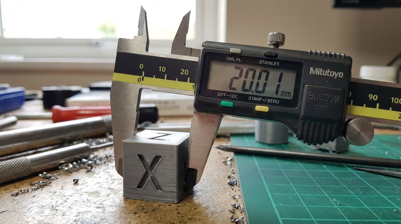
Step 1: Print a Calibration Cube
The humble calibration cube is still the gold standard for checking dimensional accuracy. Print a 20×20×20mm cube (XYZ calibration cube files are everywhere — Thingiverse, Printables, or your slicer’s built-in test objects).
Use these settings for the test print:
- Layer height: 0.2mm
- Walls: 3-4
- Infill: 20%
- Speed: moderate (50-60 mm/s outer walls)
- No brim, no raft
- Material: PLA (easiest to calibrate with first)
After printing, let the cube cool completely on the bed — measuring a warm part gives inaccurate readings because of thermal expansion. This matters more than you’d think: PLA at 40°C can be 0.1-0.15mm larger than the same part at room temperature.
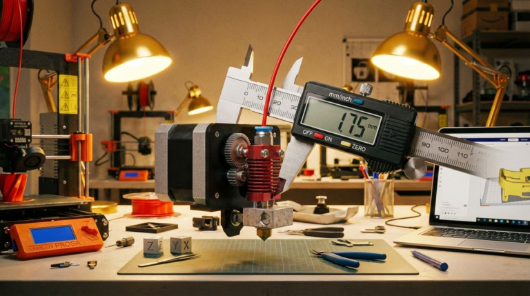
Step 2: Measure With the Right Tool
You need digital calipers. Not a ruler, not a tape measure — calipers. Decent digital calipers cost $15-25 and are the single most useful 3D printing tool you’ll ever buy. Brands like Mitutoyo are the gold standard, but even budget calipers from Amazon are accurate to ±0.02mm, which is far more precision than we need.
Measure your calibration cube in all three axes:
- X axis: Measure across the face perpendicular to the X direction
- Y axis: Measure across the face perpendicular to the Y direction
- Z axis: Measure the height
Take three measurements for each axis at different points on the face and average them. Don’t measure at the very bottom — the first few layers often have slight elephant foot expansion that doesn’t represent the overall accuracy.
Write down your numbers. For example:
- X: 20.15mm (target: 20.00mm, error: +0.15mm)
- Y: 20.08mm (target: 20.00mm, error: +0.08mm)
- Z: 20.05mm (target: 20.00mm, error: +0.05mm)
Step 3: Understand What’s Causing the Error
Before adjusting anything, understand what type of error you’re seeing:
Consistent over-sizing in X and Y (but not Z): This is almost always over-extrusion. The outer walls are wider than they should be, making the part bigger in X and Y. Fix this with flow rate calibration, not steps/mm adjustment.
Consistent under-sizing in X and Y: Under-extrusion or too much outer wall shrinkage from cooling. Check flow rate and try reducing fan speed slightly.
Z height error: This is usually a steps/mm calibration issue for the Z axis, or (less commonly) a first layer that’s too squished or too high.
X and Y differ significantly from each other: One axis has a belt tension issue or a mechanical problem. Check belt tension on both axes — they should feel similar. A loose belt causes under-sizing in that axis because the carriage doesn’t move the full requested distance.
Parts are accurate at small sizes but off at large sizes: Steps/mm calibration error. The error scales linearly with distance.
Step 4: Calibrate E-Steps (Extruder Steps)
Before touching X, Y, or Z steps, calibrate your extruder. Most dimensional errors in X and Y are caused by incorrect extrusion, not incorrect motion.
The process:
- Heat your hotend to printing temperature
- Remove the Bowden tube from the hotend (or mark the filament 120mm from the extruder inlet on a direct drive)
- Command the printer to extrude 100mm of filament (M83 then G1 E100 F100)
- Measure how much filament was actually pulled in
- Calculate: New E-steps = Current E-steps × (100 / actual distance extruded)
- Save with M92 Exx and M500
If your extruder was extruding 95mm instead of 100mm, that 5% under-extrusion was causing thin walls, gaps, and under-sized parts. Fixing this single value often resolves dimensional accuracy problems entirely.
Step 5: Calibrate Flow Rate
E-steps tell the extruder how far to turn. Flow rate (extrusion multiplier) fine-tunes how much filament actually comes out relative to what the slicer expects. Even with perfect E-steps, you may need to adjust flow rate because filament diameter varies and different materials compress differently in the extruder.
OrcaSlicer and PrusaSlicer both have built-in flow rate calibration tests. Alternatively, print a single-wall box (no infill, one wall) and measure the wall thickness with calipers. It should match your line width setting exactly.
If your line width is set to 0.4mm and the single wall measures 0.42mm, reduce flow rate by: (0.40 / 0.42) × 100 = 95.2%. Set your flow multiplier to 0.952 or 95.2%.
This is the most impactful calibration for dimensional accuracy. Get this right and most parts will be within ±0.1mm of their designed dimensions.
Step 6: Steps/mm Calibration (X, Y, Z)
If your flow rate is correct but parts are still off-dimension in a consistent way, check your steps/mm values. This tells the firmware how many stepper motor steps translate to 1mm of physical movement.
For belt-driven axes (X and Y), the steps/mm value is determined by your stepper motor (usually 200 steps/revolution), driver microstepping (usually 16x), pulley tooth count (usually 20), and belt pitch (usually 2mm GT2). The math gives you 80 steps/mm for most common configurations, and this value is mechanically fixed — it shouldn’t need adjustment unless you’ve changed hardware.
If you’re calculating steps/mm from scratch:
Steps/mm = (motor steps × microstepping) / (pulley teeth × belt pitch)
Example: (200 × 16) / (20 × 2) = 80 steps/mm
For the Z axis (usually leadscrew driven):
Steps/mm = (motor steps × microstepping) / lead
Example with 8mm lead: (200 × 16) / 8 = 400 steps/mm
Important: Never use “print a cube and adjust steps/mm to match” as a calibration method for X and Y. This masks extrusion problems and creates new issues. Steps/mm should be calculated from hardware specifications, not empirically adjusted. Only Z-axis steps/mm should be tweaked based on measurements, and only after confirming the leadscrew specs.
Step 7: Compensate for Shrinkage
Even with perfect calibration, thermoplastics shrink as they cool. Different materials shrink by different amounts:
- PLA: 0.3-0.5% shrinkage
- PETG: 0.5-0.8% shrinkage
- ABS: 0.7-1.1% shrinkage
- Nylon: 1.0-2.0% shrinkage
For PLA, shrinkage is usually small enough to ignore. For ABS and nylon, you may need to scale your model up by the shrinkage percentage. Most slicers have a “scale compensation” or “XY size compensation” setting for this purpose.
Your slicer’s XY hole compensation and XY contour compensation settings are powerful tools here. XY hole compensation enlarges holes to account for the fact that circular holes always print slightly smaller than designed (because the outer edge of the extrusion is on the inside of the circle). A value of -0.1mm to -0.2mm typically gets holes to their correct size.
Step 8: Tolerances for Assemblies
Even with perfect calibration, designing parts that fit together requires understanding tolerances:
Press fit: 0.0-0.1mm gap (parts force together and hold by friction)
Snug fit: 0.1-0.2mm gap (parts slide together with slight pressure)
Easy fit: 0.2-0.3mm gap (parts slide freely but without play)
Loose fit: 0.3-0.5mm gap (parts move freely, some play)
When designing assemblies, build tolerances into your CAD model rather than relying on the slicer to compensate. If you want a pin to slide into a hole, make the hole 0.2-0.3mm larger than the pin diameter in your design. This approach is more reliable and portable across different printers and materials.
Step 9: Verify With a Functional Test
After calibration, print something that tests real-world accuracy. The Tolerance Test by Maker’s Muse is excellent — it prints interlocking rings at different clearances so you can see exactly what tolerance your printer achieves. If the 0.2mm tolerance ring moves freely but 0.15mm is fused, you know your practical minimum tolerance.
Another good test: print a box with a separate lid designed with 0.2mm clearance. If it fits smoothly without force, your calibration is dialed in.
Advanced: Per-Material Profiles
Dimensional accuracy varies by material. A printer perfectly calibrated for PLA may print PETG parts 0.1mm oversize because PETG has different flow characteristics. The solution: create separate flow rate and compensation profiles for each material you use regularly.
Print a calibration cube in each material, measure it, and adjust that material’s flow rate and XY compensation independently. Save these as material profiles in your slicer so you don’t have to recalibrate every time you switch filaments.
Quick Reference: Calibration Order
Always calibrate in this order — each step depends on the previous ones being correct:
- E-steps (mechanical baseline)
- Flow rate (fine-tune extrusion width)
- Temperature (optimal flow and adhesion)
- XY compensation (slicer-level dimensional adjustment)
- Verify with calibration cube (confirm everything works together)
- Test with functional print (real-world validation)
Skip a step or do them out of order and you’ll be chasing calibration ghosts for weeks. Trust the process, measure carefully, and adjust methodically. Dimensional accuracy isn’t glamorous, but it’s what separates prints that work from prints that almost work.