Best Print Orientation for Strength: How Layer Direction Affects 3D Print Durability
Why Print Orientation Matters More Than You Think
You’ve spent hours perfecting your slicer settings — temperature, speed, retraction — everything is dialed in. But your functional parts keep breaking. The problem might not be your settings at all. It might be how you’re orienting your model on the build plate.
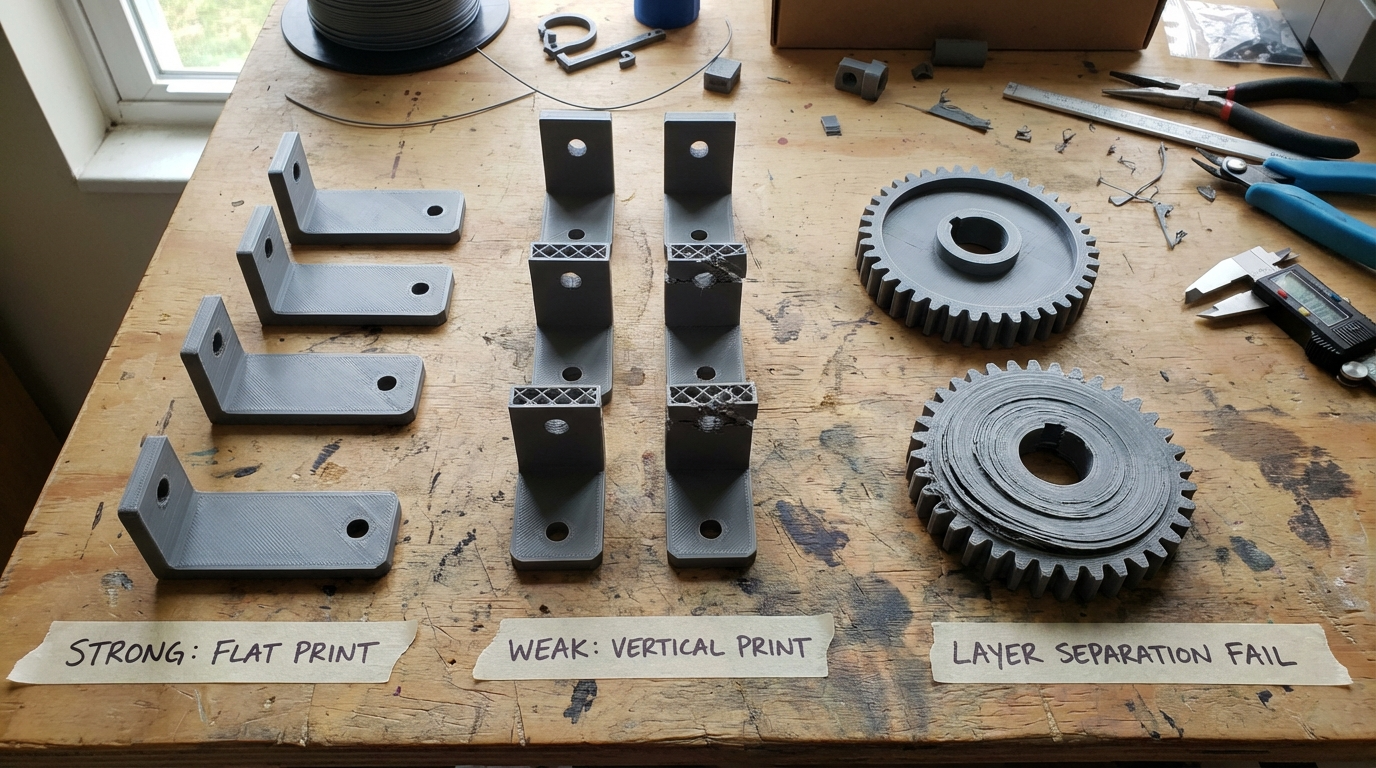
FDM 3D printing creates parts by stacking layers of plastic. This layer-by-layer construction means your parts have a strong direction and a weak direction, just like wood has grain. Print a bracket with the load going across the layers, and it might snap with hand pressure. Print the same bracket with the load running along the layers, and it can support 10 times the weight.
Understanding this “grain” effect and using it to your advantage is one of the biggest free upgrades you can give to your functional prints. No new filament needed, no hardware upgrades — just smarter orientation choices in your slicer.
The Anisotropy Problem: Strong vs Weak Directions
FDM parts are anisotropic, meaning their mechanical properties differ depending on the direction you measure them. Specifically:
- X-Y plane (along layers): Strong. The continuous filament lines carry load effectively
- Z axis (between layers): Weak. Inter-layer adhesion is the limiting factor. Parts fail by delaminating — layers separating from each other
In real numbers, the Z-axis tensile strength of a typical PLA part is only 30-50% of its X-Y strength. For PETG, it’s around 40-60%. For ABS, roughly 35-55%. This means orientation alone can double the strength of your part in the direction that matters.
The reason is simple: within a layer, you have continuous strands of plastic bonded side-by-side. Between layers, you have thermal bonds where one layer fuses to the one below it. These thermal bonds are never as strong as the continuous material, no matter how well you tune your temperatures.

The Golden Rule: Layers Perpendicular to the Load
Here’s the fundamental principle: orient your part so that the primary load or stress runs parallel to the layers, not across them.
In other words, the force should travel along the layer lines, not try to pull layers apart. If a part will be pulled, bent, or stressed in a particular direction, make sure the layers run in that same direction.
Example: A Simple Hook
Imagine a wall hook that holds a coat. The weight pulls straight down. If you print the hook standing upright (as it would mount on the wall), the layers stack horizontally. The downward force runs perpendicular to the layers — the weakest direction. The hook snaps at the curved section where layers separate.
Now print the same hook lying on its side, with the hook curve flat on the bed. The layers stack vertically relative to the hook’s orientation. The downward force when mounted runs parallel to the layers. The hook is dramatically stronger.
Example: A Shelf Bracket
An L-shaped shelf bracket supports weight pushing down on the horizontal arm. Print it standing up (L shape upright), and the bend point where the two arms meet is the weakest spot — layers want to split apart right at the corner. Print it flat on its back, and the layers run the length of both arms, making the critical bend much stronger.
Common Parts and Their Ideal Orientations
Here’s a quick reference for parts you’ll encounter frequently:
Clips, Clamps, and Snap-Fits
These parts flex repeatedly. Orient so the flexing motion bends along the layers, not across them. For a spring clip that flexes open and closed, the layers should run along the length of the clip arm. Cross-layer flex will crack within a few cycles; along-layer flex can survive thousands.
Gears and Rotating Parts
Print gears flat on the bed (axis vertical). This puts all the tooth loads in the X-Y plane where the material is strongest. Gears printed on their side (axis horizontal) will have weak teeth that shear off under load.
Tubes and Cylindrical Parts
For tubes under internal pressure (like plumbing fittings), print vertically (tube standing up). The hoop stress from internal pressure runs around the circumference — along the layers. Print horizontally, and the pressure tries to split layers apart along the length.
For tubes under bending loads (like a handlebar), print horizontally so the layers run along the length and resist the bending.
Enclosures and Boxes
Boxes are usually loaded by whatever sits inside them or on top. Print with the largest flat face on the bed. This maximizes the contact area with the bed (better adhesion), puts the most layers in the walls (stronger sides), and distributes any top loads across many layers.
Flat Plates and Panels
Print flat on the bed. This is obvious for geometry reasons, but it also means any bending loads on the plate are resisted by continuous layer lines running the full width. A panel printed on edge would be very weak in bending.
When Strength and Printability Conflict
Sometimes the strongest orientation is the hardest to print. Overhangs, support requirements, and surface finish all compete with strength optimization. Here’s how to balance them:
The Overhang Problem
The ideal orientation for strength might put steep overhangs in difficult positions, requiring heavy support material. Every supported surface has a rough finish where supports contact the part, and support removal can introduce small defects that weaken the part.
Strategy: Accept supports when the part’s function requires maximum strength. Use support interface layers (2-3 dense layers between support and part) to minimize surface damage. Tree supports generally leave less scarring than grid supports.
The Surface Finish Tradeoff
Layer lines are most visible on curved surfaces printed at angles. If your part has a cosmetic face, you might want that face on the bed (smooth) or perpendicular to the layers (smoother curves). This might conflict with the strongest orientation.
Strategy: Decide what matters more — strength or appearance. For functional parts, always prioritize strength. For display pieces with no load requirements, prioritize appearance. For parts that need both, consider post-processing (sanding, filler, paint) to improve the finish of a strength-optimized orientation.
The Bed Adhesion Factor
Tall, narrow parts are prone to tipping, warping, and adhesion failures. Sometimes the strongest orientation makes the part tall and skinny.
Strategy: Use a brim (8-15mm) for stability. Consider splitting the part and printing the pieces in their optimal orientations, then joining them with adhesive or mechanical fasteners.
Advanced Orientation Strategies
Split and Rejoin
Complex parts often can’t be printed in a single orientation that works for all load paths. The solution: split the model at strategic points, print each section in its optimal orientation, and join them.
Joining methods:
- Cyanoacrylate (super glue): Quick, strong enough for light loads. The bond is brittle
- Epoxy: Strongest adhesive option. Fills gaps and creates flexible, durable bonds
- Solvent welding: For ABS (acetone) or PETG (MEK). Creates a true molecular bond as strong as the base material
- Mechanical fasteners: Bolts through heat-set inserts provide the strongest and most reliable joints
Variable Wall Thickness
If your slicer supports it, you can increase wall thickness in the orientation where inter-layer strength is a concern. More perimeters means more material resisting delamination forces. Going from 2 walls to 4 walls in the critical direction can compensate for the inherent weakness.
Infill Orientation
Some slicers let you control infill line direction. For parts where the load direction is known, aligning the infill lines with the load path adds strength. This is especially effective with higher infill percentages (40%+) and rectilinear infill patterns.
Testing Your Orientation Choice
Not sure which orientation is best? Print test specimens and break them.
- Design a simple test bar — a rectangular bar 100x20x5mm works well
- Print it in multiple orientations — flat, on edge, and standing up
- Break each one by clamping one end and pushing down on the other (a crude but effective 3-point bend test)
- Note which orientation breaks last and at what approximate force
You’ll be surprised how dramatic the difference is. The strongest orientation often holds 3-5 times the load of the weakest, even though the parts look identical.
Material-Specific Orientation Notes
- PLA: Brittle. Orientation matters most here because PLA cracks rather than deforms. A poorly oriented PLA part breaks; a well-oriented one holds
- PETG: More forgiving due to its slight flexibility. Inter-layer adhesion is naturally better than PLA. Still benefits significantly from correct orientation
- ABS: Good inter-layer adhesion when printed in an enclosure. The gap between X-Y and Z strength is smaller than PLA, but still significant
- Nylon: Excellent inter-layer adhesion. Orientation matters less for nylon than for any other common filament, but it still helps
- TPU: Flexible, so rarely breaks due to delamination. Orientation choices for TPU are more about printability than strength
- Carbon Fiber Composites: Orientation matters enormously. The fibers align along the print direction, creating extreme anisotropy. A CF part is incredibly stiff along the extrusion lines and much weaker across them
Quick Decision Framework
When you load a model into your slicer, ask these three questions in order:
- Where does the load come from? Identify the primary force direction
- Orient layers parallel to the load so the force runs along the layer lines
- Check printability. Can it actually print in this orientation? Overhangs? Adhesion? Supports? If not, find the next best orientation that compromises least on strength
This simple three-step process takes 30 seconds and can mean the difference between a part that fails on first use and one that lasts for years.
Final Thoughts
Print orientation is the most underutilized tool in the 3D printing toolkit. Most people drop their model into the slicer in whatever orientation it imported and hit print. Taking a moment to think about how forces will act on the finished part — and orienting it accordingly — costs nothing and can dramatically improve strength.
Remember the golden rule: layers parallel to the load, not perpendicular. When in doubt, think about where you’d expect the part to break, and make sure the layers don’t run across that break line. With this one principle, you’ll produce functional parts that actually work as intended.