How to Design 3D Models for Easy FDM Printing: Tips and Rules
You can have the best 3D printer in the world with perfectly tuned settings, but if your model isn’t designed with FDM printing in mind, you’re going to have a bad time. Designing for 3D printing is a skill that separates frustrating failed prints from clean, reliable parts that pop off the bed ready to use. Whether you’re working in Fusion 360, TinkerCAD, FreeCAD, or any other CAD tool, these practical design rules will save you hours of troubleshooting.
Understanding FDM Constraints
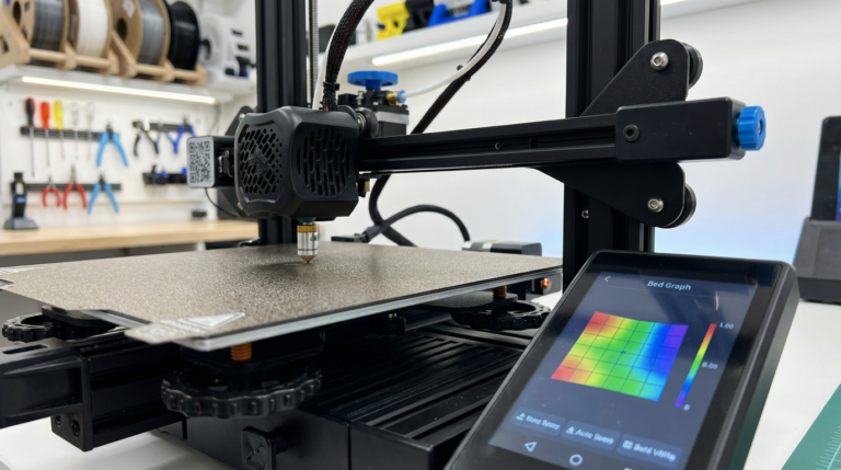
Before we get into specific tips, it helps to remember how FDM 3D printing actually works. Your printer builds parts layer by layer from the bottom up, extruding melted plastic through a nozzle. This means:
- Each layer needs something beneath it — you can’t print on thin air (well, not much)
- The nozzle has a minimum feature size — typically 0.4mm width
- Parts are weakest along the Z-axis — layers can separate under stress
- Gravity is always present — overhangs and bridges have limits
Every design tip in this article connects back to these physical realities.
The 45-Degree Overhang Rule
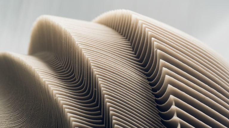
This is the foundational rule of designing for FDM. Your printer can handle overhangs up to about 45 degrees from vertical without supports. Beyond that angle, the extruded plastic has too little surface to bond to and you get droopy, ugly overhangs.
What does this mean for your designs?
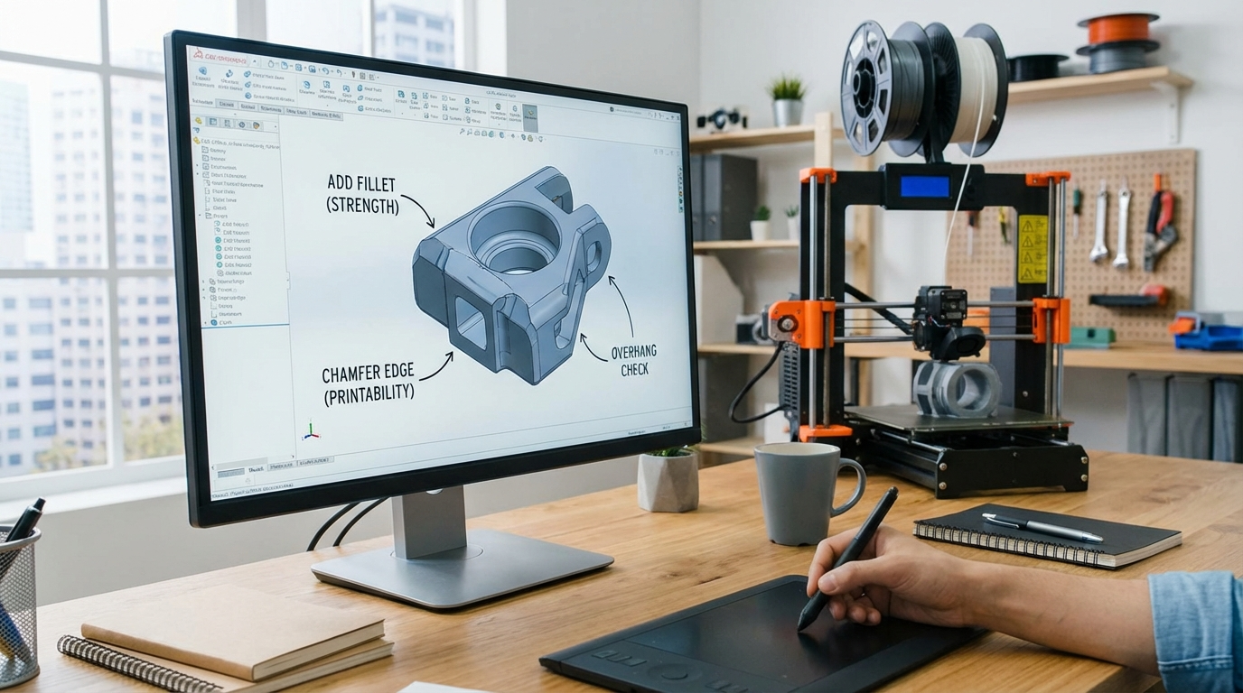
- Chamfers over fillets on bottom edges. A 45° chamfer is self-supporting. A radius fillet on a bottom edge requires supports. This single change eliminates supports from most functional designs.
- Angled walls instead of sharp overhangs. If a feature extends outward, taper it at 45° or less rather than making a sharp horizontal ledge.
- Think about print orientation early. Sometimes rotating a model 90° eliminates all overhangs. Design with a specific print orientation in mind.
Minimum Wall Thickness and Feature Size
Your nozzle diameter sets the minimum wall thickness. With a standard 0.4mm nozzle:
- Minimum wall thickness: 0.8mm (2 perimeters). Single-perimeter walls (0.4mm) are technically possible but fragile and prone to gaps.
- Recommended wall thickness: 1.2mm (3 perimeters) for structural parts
- Minimum hole diameter: 2mm. Holes smaller than this tend to close up during printing
- Minimum gap between features: 0.4mm (one nozzle width). Anything smaller will fuse together
- Minimum text height: 6mm for embossed text, 8mm for engraved text (at 0.4mm nozzle)
Tip: If you need fine details smaller than these minimums, consider using a smaller nozzle (0.2mm), switching to resin printing for that part, or designing the detail as a decal/label instead.
Designing Strong Parts: Orientation and Geometry
FDM parts have an inherent weakness: layer adhesion is always weaker than the material itself. A part might handle 50kg of force along the XY plane but snap at 5kg of force along the Z-axis (pulling layers apart).
Design Strategies for Strength
Orient critical loads along the XY plane. If a bracket is going to be pulled sideways, print it so the layers run perpendicular to the pull direction. The strongest orientation puts stress along the layers, not between them.
Use fillets and rounds on interior corners. Sharp interior corners create stress concentrations that cause cracks. A simple 2mm fillet radius on internal corners can double the strength of a part.
Add gussets and ribs. Instead of making walls thicker (which uses more material and time), add triangular gussets at 90° joints or ribs along flat surfaces. A 2mm-thick wall with ribs is lighter and stiffer than a 4mm-thick solid wall.
Design with draft angles. Parts that taper slightly (1–3° draft angle) are easier to print and less likely to warp than perfectly vertical walls. This is especially useful for tall, thin parts.
Hole and Pin Tolerances
If you’re designing parts that fit together — snap fits, pin joints, press-fit assemblies — you need to account for the dimensional inaccuracy of FDM printing.
- Holes shrink: FDM-printed holes are typically 0.1–0.3mm smaller than designed. If you need a 5mm hole, model it at 5.2–5.3mm.
- Pins expand: Similarly, cylindrical pins print slightly larger than designed. Model pins 0.1–0.2mm smaller than the target diameter.
- Press-fit interference: For a press fit, use 0.1–0.15mm interference (pin larger than hole). For a slip fit, use 0.2–0.3mm clearance.
- Horizontal holes are oval: Holes printed in the XY plane (horizontal holes) will be slightly oval due to layer stacking. Use teardrop-shaped holes for horizontal features to maintain roundness without supports.
Print a tolerance test first. Before committing to a complex multi-part assembly, print a quick tolerance test with various gap sizes to calibrate your specific printer’s accuracy.
Snap Fits and Living Hinges
Snap fits are incredibly useful for 3D printed enclosures and assemblies, but they require careful design:
- Cantilever snap fits work best with FDM. Design the flexible arm with a length-to-thickness ratio of at least 5:1 (e.g., 10mm long, 2mm thick).
- Add a generous radius at the base of the snap arm — this is where stress concentrates and parts crack.
- Print the snap arm along the XY axis, never along Z. A snap arm printed vertically will break immediately because you’re pulling layers apart.
- Use PLA+ or PETG for snap fits. Standard PLA is too brittle and will crack on the first or second use.
Living hinges (thin flexible sections that allow repeated bending) are possible with TPU and polypropylene filament, but generally don’t work well with PLA or PETG. For hinges in rigid materials, design a pin-and-socket hinge instead.
Support-Free Design Tricks
Supports work, but they leave marks, waste material, and add post-processing time. Here are tricks to avoid them entirely:
- Bridge instead of overhang. FDM printers can bridge gaps up to 50–80mm (material dependent). If you have a horizontal ceiling, design it to bridge between two walls rather than overhang from one side.
- Use the 45° rule aggressively. Slopes, chamfers, and gradual transitions are your friends. Convert any shelf or ledge into a gradual slope.
- Split the model. A complex shape that requires heavy supports can often be split into two or more pieces that each print support-free. Glue or bolt them together after printing.
- Teardrop holes. Replace horizontal circular holes with teardrop shapes (flat top at 45°). They print without supports and still accept bolts and pins.
- Elephant ears vs. overhangs. If a horizontal surface is unavoidable, add small 45° support tabs in the model itself that can be trimmed off after printing. This gives you control over where supports go and how clean the result is.
Designing for Assembly
If your project involves multiple printed parts that connect together:
- Design alignment features. Add registration pins, lips, or tongue-and-groove joints so parts can only fit together one way and align perfectly.
- Include bolt holes. Heat-set threaded inserts are the gold standard for strong, reusable bolt connections in 3D prints. Design holes 0.1–0.2mm smaller than the insert for a solid press fit when installed with a soldering iron.
- Allow for gluing surfaces. If parts will be superglued or epoxied together, design flat mating surfaces with a small recessed channel for excess glue to squeeze into.
- Number your parts. For complex assemblies, add small embossed or engraved numbers on hidden surfaces so you know which part goes where during assembly.
Common Design Mistakes to Avoid
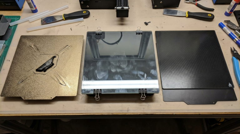
Flat bottoms on everything. Your first layer is your foundation. If a model doesn’t have a flat bottom, it either needs supports or a brim. Design a flat base wherever possible.
Ignoring print orientation. A part that looks beautiful in CAD might be impossible to print well in any orientation. Always think about how each feature will be built layer by layer.
Over-tight tolerances. FDM printing has resolution limits. Don’t design 0.05mm tolerances when your printer’s accuracy is ±0.2mm. Save tight tolerances for CNC or resin printing.
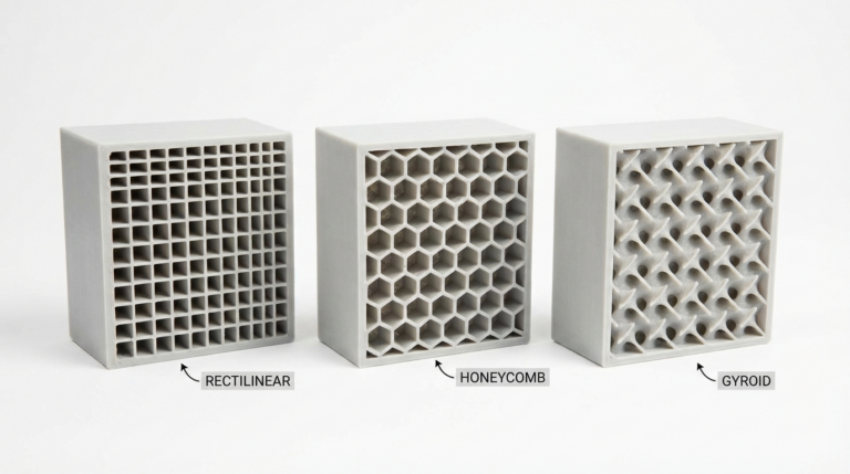
Massive solid parts. Large solid sections waste filament, take forever to print, and are prone to warping. Use internal ribs, honeycomb patterns, or appropriate infill instead of solid blocks.
Sharp external corners at the bottom. The first layer squishes outward slightly (elephant foot). Add a small 0.5mm chamfer on bottom edges in your model to compensate.
Design Software Recommendations
Your choice of CAD software matters less than understanding these principles, but here are solid options:
- Fusion 360: The most popular choice for functional part design. Parametric modeling, great for mechanical parts, free for hobbyists.
- TinkerCAD: Perfect for beginners and simple geometric designs. Browser-based, zero learning curve.
- FreeCAD: Open-source parametric modeler. Steeper learning curve but no licensing restrictions.
- Blender: Best for organic shapes and artistic models. Not ideal for precision mechanical parts.
- OpenSCAD: Code-based modeling for engineers who think in parameters and equations.
Final Tips
Iterate fast. Don’t try to get the perfect design on the first attempt. Print a quick test at low infill, check the fit and features, adjust, and reprint. This is the advantage of 3D printing — iteration costs almost nothing.
Learn from failed prints. Every failed print teaches you something about design constraints. Take a photo, note what went wrong, and adjust the design accordingly.
Share your designs. The 3D printing community on Printables, Thingiverse, and MakerWorld is incredibly generous. Sharing your designs and learning from others accelerates everyone’s skills.
Designing for 3D printing is a skill that improves with every part you make. Start with these guidelines, adapt them to your specific printer’s quirks, and you’ll be producing clean, functional parts with minimal headaches in no time.