Input Shaping Explained: How Vibration Compensation Improves 3D Print Quality
You finally dialed in your retraction, leveled the bed perfectly, and calibrated your flow rate. The print looks great — at 60mm/s. Then you bump the speed to 150mm/s and suddenly every sharp corner has ghostly echoes rippling across the surface. Those ripples have a name: ringing. And the fix has a name too: input shaping.
Input shaping — also called vibration compensation — is the single biggest quality improvement you can make when printing at higher speeds. It’s not a hardware upgrade. It’s math. And once you understand how it works, you’ll wonder why every printer doesn’t ship with it enabled.
What Is Ringing (And Why Does It Happen)?
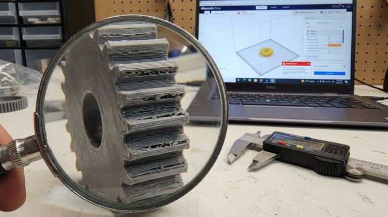
When your print head makes a sudden direction change — hitting a sharp corner, for example — the frame and belts don’t stop instantly. They vibrate. The print head oscillates back and forth at the printer’s natural resonant frequency, typically somewhere between 30-80Hz depending on your machine.
These oscillations leave visible marks on the print surface: repeated ripples that fade as they move away from the corner. The pattern looks like the corner’s shape echoing across the wall, which is why it’s also called ghosting.
At slow speeds, the vibrations are tiny and barely visible. But increase your speed and acceleration, and the vibrations get proportionally larger. At 200mm/s with high acceleration values, ringing can be severe enough to ruin surface quality entirely.
The traditional solution was simple: print slower. Keep acceleration low. Accept that speed and quality were opposing forces.
Input shaping changed that equation.
How Input Shaping Works
Input shaping is a vibration compensation algorithm originally developed for industrial CNC machines and robotic arms in the 1990s. The core idea is counterintuitive but elegant: instead of trying to dampen vibrations after they occur, you modify the movement commands to prevent the vibrations from happening in the first place.
Here’s the simplified version. Your printer’s frame has a natural resonant frequency — say 45Hz. When the print head hits a corner, it sends a pulse of energy into the frame at that frequency, causing oscillation. Input shaping splits every movement command into two (or more) carefully timed impulses. The second impulse is timed so that its vibration exactly cancels the vibration from the first impulse.
Think of it like noise-canceling headphones for your printer’s motion system. The algorithm generates an “anti-vibration” signal that destructively interferes with the resonance.
The Math (Simplified)
The most common input shaping algorithms used in 3D printing are:
ZV (Zero Vibration): The simplest shaper. Splits each impulse into two, timed at half the resonant period apart. Reduces vibration significantly but offers the least tolerance for frequency estimation errors.
MZV (Modified Zero Vibration): Uses three impulses instead of two. More tolerant of frequency estimation errors than ZV, with slightly more smoothing of sharp corners.
EI (Extra-Insensitive): Three impulses with wider tolerance for frequency errors. Good when your resonant frequency varies (temperature changes, different filament weights, etc.), but smooths corners slightly more than MZV.
2HUMP_EI and 3HUMP_EI: Even more robust to frequency errors, but with progressively more corner smoothing. These are the “nuclear option” — they’ll eliminate ringing even if your frequency measurement is off by 20%, but fine details get slightly softened.
The tradeoff across all shapers is the same: more aggressive vibration suppression means slightly more rounding of sharp corners. In practice, the difference between MZV and EI is subtle enough that most people won’t notice on functional prints.
What You Need for Input Shaping
Firmware That Supports It
Klipper has the most mature and capable input shaping implementation. It’s where the feature became mainstream in 3D printing, and it remains the gold standard. Klipper’s input shaper module supports all the algorithms mentioned above and integrates directly with accelerometer-based calibration.
Marlin added input shaping support in version 2.1.x for 32-bit boards. The implementation works but is more limited — fewer algorithm options, less automated calibration, and higher computational overhead since everything runs on the mainboard processor.
RRF (RepRapFirmware) also supports input shaping on Duet boards, with a solid implementation that’s been refined over several versions.
For this guide, I’ll focus on Klipper since it’s the most common platform for input shaping and has the best tooling for calibration.
An Accelerometer (Strongly Recommended)
You can technically set up input shaping by printing test patterns and visually estimating your resonant frequency. But an accelerometer makes the process precise, fast, and repeatable.
The ADXL345 is the standard choice — it’s the accelerometer Klipper’s documentation is built around. You can get one for $3-8, and it connects to your Raspberry Pi via SPI. Some newer printer boards (like the BTT EBB36/42 toolhead boards) have an ADXL345 built in.
The LIS2DW12 is a newer alternative that some toolhead boards use. Klipper supports it natively.

Mounting Hardware
The accelerometer needs to be rigidly mounted to your print head during calibration. A loose mount will give you garbage data. Most people either:
- 3D print a mount specific to their toolhead (STLs available on Printables for most popular setups)
- Use double-sided tape temporarily (works fine if it’s firmly attached)
- Use a toolhead board with built-in accelerometer (no mounting needed)
Step-by-Step Setup on Klipper
Step 1: Wire the Accelerometer
For an ADXL345 connected to a Raspberry Pi:
ADXL345 → Raspberry Pi
VCC    → 3.3V (Pin 1)
GND    → GND (Pin 6)
CS     → GPIO24 (Pin 18) — or your chosen CS pin
SDO    → MISO (Pin 21)
SDA    → MOSI (Pin 19)
SCL    → SCLK (Pin 23)
Step 2: Configure Klipper
Add to your printer.cfg:
[mcu rpi]
serial: /tmp/klipper_host_mcu

[adxl345]
cs_pin: rpi:None

[resonance_tester]
accel_chip: adxl345
probe_points:
    150, 150, 20  # Center of your bed
You’ll also need the Linux SPI driver enabled. Run:
sudo raspi-config
# Navigate to Interface Options → SPI → Enable
And install the required Python library:
~/klippy-env/bin/pip install numpyRestart Klipper after making these changes.
Step 3: Verify the Accelerometer
In your Klipper console (Mainsail or Fluidd), run:
ACCELEROMETER_QUERYYou should see three axes of data (X, Y, Z) with non-zero values. If you get an error, check your wiring and SPI configuration.
Step 4: Run the Resonance Test
Mount the accelerometer firmly on your print head, then run:
SHAPER_CALIBRATEThis command does everything automatically:
- Vibrates the print head across a range of frequencies on the X axis
- Measures the resonance response
- Repeats for the Y axis
- Calculates the optimal shaper type and frequency for each axis
- Outputs recommendations
The test takes about 2-3 minutes. Your printer will make some unusual noises — that’s normal. It’s deliberately vibrating the axes to measure the response.
Step 5: Apply the Results
Klipper will output something like:
Recommended shaper_type_x = mzv, shaper_freq_x = 57.4
Recommended shaper_type_y = ei, shaper_freq_y = 42.8
Add these to your printer.cfg:
[input_shaper]
shaper_freq_x: 57.4
shaper_type_x: mzv
shaper_freq_y: 42.8
shaper_type_y: ei
Save and restart Klipper.
Step 6: Print a Test
Print a calibration cube or a benchy at your target speed. Compare it to one printed without input shaping. The ringing on corners should be dramatically reduced or completely eliminated.
Understanding the Calibration Output
Klipper’s SHAPER_CALIBRATE generates detailed data. Understanding it helps you make better tuning decisions.
Resonant frequency: This is the frequency where your printer vibrates most. Different axes almost always have different resonant frequencies — the X axis (moving the toolhead left-right) and Y axis (moving the bed or gantry front-back) have different masses and belt tensions.
Recommended shaper: Klipper recommends the shaper that provides the best balance of vibration reduction and minimum corner smoothing for your specific resonance profile. It’s almost always the right choice, but you can override it.
Remaining vibration %: Lower is better. Below 5% remaining vibration, ringing is essentially invisible. Klipper weights this against corner smoothing when making recommendations.
Maximum acceleration: Each shaper has a maximum recommended acceleration. Going above this value means the shaper can’t fully compensate, and some ringing may return. This is your practical acceleration limit for artifact-free printing.
Tuning Tips for Best Results
Different Shapers for Different Axes
It’s completely normal — and often optimal — to use different shaper types for X and Y. If your X axis is stiff and consistent (low frequency variation), MZV might work perfectly. But if your Y axis has more mass variation (bed slingers, where filament weight changes the bed mass), EI or 2HUMP_EI might be more appropriate for that axis.
Re-Calibrate After Hardware Changes
Changed your toolhead? New belts? Different hotend? Re-run SHAPER_CALIBRATE. The resonant frequency depends on the mass and stiffness of the motion system, and any change to those properties shifts the frequency.
Temperature Matters
Belt tension changes with temperature. If you calibrate input shaping with a cold printer, the values might be slightly off when the printer is heat-soaked during a long print. For best accuracy, heat your bed and hotend to printing temperatures, let the printer soak for 10-15 minutes, then calibrate.
Don’t Chase Perfection
If Klipper recommends MZV at 57.4Hz, don’t spend three hours trying to squeeze out 0.5% less remaining vibration by manually testing every shaper. The recommendation is good enough for virtually all use cases. Print something and evaluate the actual results.
Common Problems and Solutions
Ringing Still Visible After Input Shaping
Check accelerometer mounting. A loose accelerometer during calibration gives inaccurate data. Remount firmly and recalibrate.
Check belt tension. Loose belts create inconsistent resonant frequencies that the shaper can’t fully compensate. Tighten your belts evenly and recalibrate.
Try a more robust shaper. Switch from MZV to EI, or from EI to 2HUMP_EI. More robust shapers handle frequency variation better.
Check your acceleration values. If you’re exceeding the maximum recommended acceleration from calibration, reduce your acceleration settings.
Loss of Fine Detail on Sharp Corners
This means your shaper is over-smoothing. Try a less aggressive shaper (e.g., ZV instead of MZV, or MZV instead of EI). The tradeoff is slightly more ringing tolerance, but sharper corners.
Different Results on X vs Y Axes
Completely normal, especially on bed-slinger printers where the Y axis moves a heavy heated bed. CoreXY machines tend to have more similar X/Y characteristics since the gantry moves in both directions.
Accelerometer Not Detected
Double-check SPI wiring. Ensure SPI is enabled in raspi-config. Verify the cs_pin in your config matches the GPIO pin you wired CS to. Try running ACCELEROMETER_QUERY — the error message usually points to the issue.
Input Shaping Without an Accelerometer
If you don’t have an accelerometer, you can still use input shaping — you’ll just need to estimate your resonant frequency manually.
The Ringing Test Print Method
- Print a test object with sharp corners (a calibration cube works) at moderate speed with no input shaping enabled.
- Measure the distance between ringing ripples on the surface. Use calipers for accuracy.
- Calculate the frequency:
frequency = print_speed / ringing_distance
For example, if you printed at 100mm/s and the ripples are 2mm apart:100 / 2 = 50Hz - Enter this frequency in your config and start with the EI shaper (it’s most tolerant of estimation errors).
- Print again and iterate. Adjust the frequency up or down by 2-3Hz and compare results.
This method works but is less accurate than accelerometer calibration. If you’re serious about high-speed printing, the $5 accelerometer is worth it.
Input Shaping on Marlin
Marlin 2.1.x added input shaping support for 32-bit boards. The configuration lives in Configuration_adv.h:
#define INPUT_SHAPING_X
#define INPUT_SHAPING_Y
#define SHAPING_FREQ_X 50.0  // Hz
#define SHAPING_FREQ_Y 50.0  // Hz
#define SHAPING_ZETA_X 0.15  // Damping ratio
#define SHAPING_ZETA_Y 0.15
Marlin supports ZV and EI shapers. The calibration is manual — no built-in accelerometer support. You’ll need to use the ringing test print method described above.
The key limitation: Marlin runs input shaping on the mainboard processor, which means it competes for CPU time with step generation. On some boards, enabling input shaping at high speeds can cause step timing issues. If you experience layer shifts or stuttering after enabling it, reduce your maximum speed or consider switching to Klipper where the computation runs on the more powerful host computer.
Real-World Impact: What to Expect
Let me set realistic expectations. Input shaping is not a magic bullet that makes every print perfect. Here’s what it actually does and doesn’t do.
What it fixes:
- Ringing/ghosting artifacts at corners and sharp features
- Surface quality degradation at higher print speeds
- The speed-vs-quality tradeoff (you can have both, within reason)
What it doesn’t fix:
- Layer adhesion issues
- Stringing or oozing (that’s retraction tuning)
- First layer problems (that’s bed leveling)
- Over/under-extrusion (that’s flow calibration)
- Mechanical issues like loose bolts, worn bearings, or bent lead screws
On a well-built printer with proper input shaping, you can realistically print at 150-250mm/s with surface quality comparable to 60-80mm/s without it. That’s the genuine promise, and it delivers. On premium machines like Vorons or Bambu Lab printers (which use input shaping internally), speeds of 300-500mm/s are achievable.
The improvement is most dramatic on prints with lots of sharp corners and flat surfaces where ringing is most visible — mechanical parts, boxes, cases, and calibration objects. On organic shapes with gentle curves, the difference is less noticeable since there are fewer sudden direction changes to trigger ringing.
Frequently Asked Questions
Does input shaping work on all printers?
It works on any FDM printer, but the benefit scales with your target speed. If you print at 40-60mm/s, ringing is minimal anyway and input shaping won’t make a visible difference. The feature shines when you’re pushing 100mm/s and above.
Can I use input shaping with a bed-slinger printer?
Yes, and bed-slingers often benefit the most. The heavy heated bed on the Y axis creates pronounced ringing that input shaping handles well. Just expect your Y axis to need a different (usually more robust) shaper than your X axis.
How often should I recalibrate?
Recalibrate after hardware changes, major belt tension adjustments, or if you notice ringing returning. For a stable, unmodified printer, the initial calibration stays valid for months.
Does input shaping slow down prints?
Slightly. The shaper smooths out acceleration profiles, which can add a small amount of time to prints with many sharp direction changes. In practice, the slowdown is 1-5% — negligible compared to the massive speed increase input shaping enables.
Is Klipper required for input shaping?
No. Marlin and RepRapFirmware also support it. Klipper just has the most polished implementation with the best calibration tools.
Wrapping Up
Input shaping transformed high-speed 3D printing from a compromise into a viable workflow. Before it reached consumer printers, fast printing meant accepting ugly surfaces. Now, a $5 accelerometer and a few minutes of calibration can eliminate ringing almost entirely.
If you’re running Klipper and haven’t set up input shaping yet, it should be the next thing you do. The setup takes 20 minutes, the accelerometer costs less than a spool of filament, and the results are immediately visible. It’s one of those rare upgrades where the improvement is so obvious you’ll wonder why you waited.
And if you’re still on Marlin but eyeing higher speeds, input shaping support is one of the strongest reasons to consider the switch to Klipper. The combination of input shaping, pressure advance, and Klipper’s computational headroom is what makes modern high-speed printing possible.