Print-in-Place 3D Models: How to Print Moving Parts Without Assembly
Print-in-Place 3D Models: How to Print Moving Parts Without Any Assembly
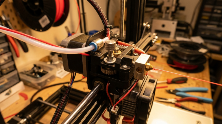
One of the most impressive capabilities of FDM 3D printing is the ability to create objects with moving parts — hinges, gears, chains, and articulated joints — in a single print with zero assembly required. These are called print-in-place models, and they showcase what 3D printing can do that traditional manufacturing cannot easily replicate. Here is your complete guide to understanding, printing, and designing them.
What Are Print-in-Place Models?
Print-in-place (PIP) models are 3D designs where multiple interlocking or articulating components are printed simultaneously as one piece. When the print finishes, the parts already move freely without any post-processing, gluing, or assembly.
Common examples include:
- Articulated animals and dragons — Flexible, segmented bodies that bend and pose
- Hinges and boxes — Lids that open and close on integrated hinges
- Gear mechanisms — Interlocking gears that rotate within a housing
- Chains — Individual links printed interlinked
- Fidget toys — Spinners, cubes, and articulated gadgets
- Ball joints — Sockets with captive balls that rotate freely
The secret behind all of these is carefully designed gaps between moving parts that are large enough to prevent fusion during printing but small enough to maintain mechanical function.
Critical Settings for Print-in-Place Success
Getting print-in-place models to work reliably requires precise slicer settings. Here are the key parameters:
Gap Tolerance
The gap between moving parts is the single most important factor. Most successful PIP designs use gaps between 0.2mm and 0.5mm. A gap of 0.3mm is the sweet spot for most printers — large enough to prevent fusion, small enough to feel solid.
If your printer is not well calibrated, start with 0.4mm gaps and work down. Over-extruding even slightly will close these gaps and fuse parts together.
Layer Height
Use a layer height of 0.2mm for most PIP prints. Thinner layers (0.12mm) give better surface quality but increase the chance of layers fusing between moving parts. Thicker layers (0.28mm) reduce fusion risk but may leave rough surfaces that create friction.
Print Speed
Slower is generally better for print-in-place models. Print at 40 to 60 mm per second for the best results. High-speed printing can cause slight positional inaccuracies that close the critical gaps between parts.
Cooling
Maximum cooling is essential. Run your part cooling fan at 100% for PLA prints. Proper cooling ensures each layer solidifies before the next is deposited, preventing the soft plastic from bridging across gaps and fusing moving parts together.
Temperature
Print at the lower end of your filament’s temperature range. For PLA, try 195 to 200 degrees Celsius instead of 210. Lower temperatures reduce oozing, which is the primary cause of parts fusing in the gaps.
Best Materials for Print-in-Place
PLA is the best material for print-in-place models. It has low warping, excellent bridging capability, and solidifies quickly with proper cooling. These properties make it ideal for maintaining the precise gaps PIP designs require.
PETG can work but is more challenging. PETG is stringier than PLA and has a tendency to ooze, which increases the risk of parts fusing. If using PETG, increase your gap tolerance to 0.4 to 0.5mm.
TPU is used for flexible print-in-place designs like articulated animals. The natural flexibility of TPU means the joints do not need to be as precise, but printing TPU requires a direct drive extruder for best results.
ABS is generally not recommended for PIP prints. Its tendency to warp and shrink makes gap dimensions unpredictable, and the lack of cooling (enclosure required) means layers stay soft longer and are more likely to fuse.
Troubleshooting Fused Parts
If your print-in-place model comes out with fused joints, try these fixes in order:
- Gentle force first — Many PIP prints need a firm twist or flex to break the thin bridges between parts. Do not be afraid to apply moderate force.
- Craft knife — Carefully run a thin blade along the seam between fused parts to separate them.
- Calibrate your printer — Print a calibration cube and measure it. If your 20mm cube comes out at 20.1mm or larger, your printer is over-extruding, which closes gaps.
- Reduce flow rate — Drop flow rate by 2 to 5% in your slicer settings.
- Increase gap tolerance — If your printer consistently fuses parts, adjust the model’s gap tolerance up by 0.1mm.
Where to Find Print-in-Place Models
The best sources for free and premium PIP models include:
- Printables.com — Extensive library of community-designed PIP models with print settings recommendations
- Thangs.com — Growing collection with good search filtering for articulated and PIP designs
- MakerWorld — Bambu Lab’s model platform with verified print profiles for PIP models
- Thingiverse — The original repository still has thousands of classic PIP designs
Search for terms like “print in place,” “articulated,” “no assembly,” or “fidget” to find the widest selection.
Designing Your Own Print-in-Place Models
If you want to create your own PIP designs, keep these principles in mind:
- Use 45-degree angles on surfaces that bridge across gaps. This ensures printability without supports.
- Design for vertical assembly — Parts that interlock in the Z-axis (layer direction) are easier to print than those interlocking horizontally.
- Test tolerance with a simple model first — Print a basic tolerance test with gaps from 0.1mm to 0.5mm to find your printer’s sweet spot before designing complex mechanisms.
- Avoid thin pins — Hinge pins should be at least 3mm in diameter for structural integrity.
- Round all moving surfaces — Sharp corners in joint areas create stress concentrations and printing artifacts.
Final Thoughts
Print-in-place models represent one of the most satisfying aspects of 3D printing. There is something genuinely magical about pulling a fully functional mechanism off the build plate with no assembly required. With proper calibration and the right slicer settings, any well-maintained FDM printer can produce impressive PIP prints. Start with a simple articulated animal or hinge box, dial in your settings, and then explore the incredible variety of designs available in the community.