Z Wobble and Z Banding: How to Fix It for Good
By Mike Reynolds
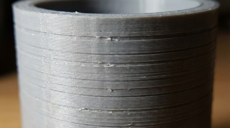
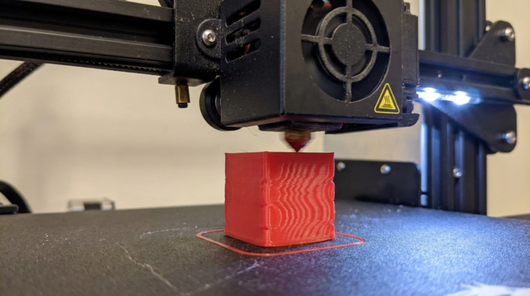
Z wobble and Z banding can ruin an otherwise perfect print. You’ll see repeating horizontal lines, ripples, or a “stair‑step” texture on vertical walls. The pattern often matches the pitch of your lead screw. The good news: Z banding is almost always mechanical and fixable. In this guide I’ll show you the exact checks and fixes that solve 90% of Z wobble problems.
What Z Wobble Looks Like
- Regular, repeating horizontal lines on vertical surfaces.
- A pattern that repeats every 8 mm, 4 mm, or the exact lead screw pitch.
- Walls that feel smooth in some areas and ridged in others.
- Inconsistent layer heights even though the slicer settings are unchanged.
If the pattern is random, it’s usually extrusion or temperature. If it’s repeating, think mechanics.
Root Causes of Z Wobble and Banding
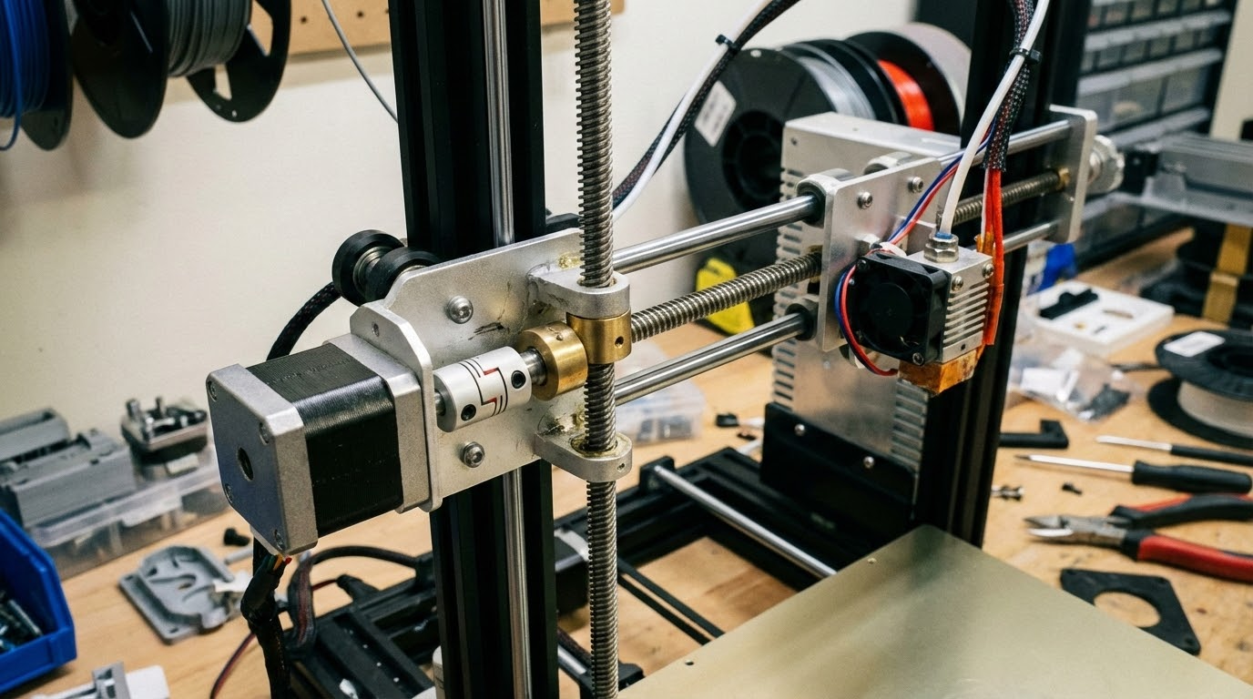
- Misaligned lead screw causing the X‑gantry to sway as it rises.
- Coupler issues between the motor and lead screw (too tight, too loose, or bent).
- Lead screw not straight (even new screws can be slightly bent).
- Over‑constrained lead screw locked at both ends instead of floating.
- Dirty or dry lead screw creating uneven friction.
- Wobbly Z‑axis guides (loose wheels or bearings).
Quick Visual Tests
Run these tests before you change anything:
- With the printer off, rotate the lead screw by hand. Watch the top of the screw. If it traces a circle, it’s bent or misaligned.
- Grab the X‑gantry and gently wiggle it. Any side‑to‑side play means loose wheels or bearings.
- Move the gantry up and down slowly. If it binds, the lead screw or nuts are misaligned.
Step‑by‑Step Fixes
1) Loosen and Re‑align the Z‑Axis
Start by loosening the lead screw coupler and the lead screw nut (if your printer allows adjustment). Move the gantry to the middle of the Z travel, then re‑tighten the coupler without forcing alignment. The goal is to let the lead screw find its natural center.
2) Don’t Over‑Constrain the Lead Screw
Many printers come with a top Z‑axis brace. If the screw is slightly bent, that brace forces it into a wobble. Counterintuitive fix: remove the top brace or loosen it so the lead screw can float. A floating lead screw often produces smoother walls.
3) Check the Coupler
Couplers should be snug, not crushed. If you overtighten, you can bend the lead screw or push it off center. If it’s too loose, the screw can wobble freely. A good coupler is flexible enough to absorb minor misalignment.
4) Lubricate the Lead Screw
Dry lead screws create uneven friction that shows up as banding. Clean with isopropyl alcohol, then apply a light machine oil or synthetic grease designed for lead screws. Wipe excess to avoid dust buildup.
5) Tighten Z‑Axis Wheels or Bearings
On V‑wheel systems, adjust the eccentric nuts until the wheels are snug but still roll smoothly. If you can spin a wheel freely with your finger while the gantry is stationary, it’s too loose.
Slicer Settings That Can Hide or Expose Banding
Mechanical issues are primary, but slicer settings can make banding more visible:
- Layer height: very tall layers (0.28–0.32) make banding more obvious.
- Wall count: thin walls show defects more than thicker walls.
- Speed: very high speeds can add vibration artifacts.
If you need a temporary workaround, drop layer height to 0.16–0.20 mm and increase wall count. It won’t fix wobble, but it will mask it.
Advanced Fixes (When the Basics Don’t Work)
Replace the Lead Screw
Some stock lead screws are simply bent. If you can see visible runout at the top, replacement is the fastest fix. T8 lead screws are cheap, and a straight screw makes a night‑and‑day difference.
Install an Oldham Coupler
An Oldham coupler decouples the motor shaft from the lead screw and allows slight lateral movement. It’s one of the best upgrades for stubborn Z wobble on machines like the Ender 3.
Upgrade to Dual Z‑Axis (Carefully)
Dual Z can improve stability, but only if both sides are perfectly aligned. If they’re out of sync, you can create new banding issues. Use a sync belt or a dual‑motor controller with auto‑alignment.
Z Wobble vs. Extrusion Issues
Over‑ or under‑extrusion can look like banding, but the pattern is usually random. Z wobble repeats at a consistent interval. If the spacing matches your lead screw pitch (often 8 mm), it’s mechanical.
Quick Troubleshooting Checklist
- Lead screw straight and clean
- Coupler snug, not over‑tight
- Top brace removed or loosened (if needed)
- Z‑axis wheels tight and smooth
- Gantry moves freely without binding
Final Thoughts
Z banding is frustrating because it looks like a complex problem, but it almost always comes down to alignment and motion. Start with the simple fixes, avoid over‑constraining the lead screw, and you’ll see dramatic improvement. Once you’ve fixed the Z‑axis, everything else—from surface finish to dimensional accuracy—gets better.
Detailed Alignment Guide (10‑Minute Tune‑Up)
- Power off and lower the gantry. Bring the X‑gantry to about 30–50 mm above the bed. This is your “neutral” zone for alignment.
- Loosen the lead screw nut screws slightly. The nut should be able to shift a tiny bit. Don’t remove it—just loosen.
- Loosen the motor coupler. Separate the lead screw from the motor shaft.
- Manually rotate the lead screw. Spin it slowly and watch the top. If it wobbles, note the high spot; you’ll use that to set your coupler position.
- Re‑connect the coupler. Slide the lead screw in so it sits centered, then tighten the coupler. Avoid pulling the screw sideways.
- Re‑tighten the lead screw nut. Keep it snug but not over‑tight. It should guide the screw, not clamp it.
- Check gantry motion. Move the gantry up and down by hand. It should feel smooth with no binding.
This small routine solves most Z banding issues on the first try. If the problem persists, look at the screw itself and the Z‑axis wheels.
Common Mistakes That Cause Z Banding
- Over‑tightening the coupler: It deforms the lead screw and introduces wobble.
- Locking the top of the lead screw: A rigid top brace makes a bent screw worse.
- Ignoring X‑gantry sag: If the gantry droops on one side, your layers will shift as it rises.
- Mixing lead screw types: Mismatched pitch or diameter on dual Z systems creates repeating artifacts.
FAQ: Z Wobble and Banding
Does printing slower fix Z wobble?
Not really. Slow speeds can mask vibration artifacts but won’t fix mechanical wobble. The pattern will still be there.
Should I grease the lead screw?
Yes, but lightly. A thin layer of synthetic grease or machine oil reduces friction without attracting too much dust.
What if the pattern repeats every 2 mm?
That often points to extruder issues or micro‑stepping artifacts rather than the lead screw. Check extrusion consistency and stepper driver settings.
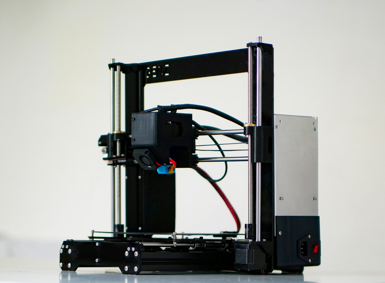
Case Study: Ender 3 Z Banding
On a stock Ender 3, I saw a repeating pattern every 8 mm. The lead screw looked “straight enough,” but the top brace forced it into a slight arc. I removed the brace, cleaned and lubricated the screw, and re‑aligned the coupler. The banding all but disappeared. That fix took 12 minutes and saved a whole spool of wasted prints.
Print Test to Confirm the Fix
After changes, print a tall calibration tower or a simple cylinder. Use 0.2 mm layers and moderate speed. If the walls look clean and the pattern is gone, you’re done. If the pattern remains but shifted, the lead screw is likely bent and should be replaced.
Extra Stabilization Tips
If you’re still seeing faint banding, check the rest of the motion system. Loose belts on X or Y can add ghosting that looks like Z wobble. Also inspect the frame for loose screws; a slightly twisted frame can push the Z‑axis out of square and create a repeating pattern as the gantry climbs.
For dual‑Z machines without a sync belt, re‑square the gantry every few weeks. I like to drop the gantry onto two identical blocks (or printed spacers) at the same height, then tighten both Z couplers. This keeps the left and right sides aligned and prevents one side from “leading” the other.
Finally, check your Z‑axis stepper motor mounts. A motor that’s slightly angled can tilt the lead screw and create a wobble pattern. Loosen the motor screws, align the shaft with the lead screw, and re‑tighten evenly.
Once you’ve fixed the mechanics, print a vase mode cylinder. It’s the fastest way to see surface quality changes because there are no infill or seam artifacts. A clean spiral wall means your Z‑axis is finally behaving.
If you’re chasing perfection, measure the lead screw runout with a dial indicator. It sounds overkill, but it quickly tells you whether the screw is the culprit. A straight screw and a relaxed mount are the cleanest path to smooth walls.