3D Print Snap Fit Joints: Design Guide for Perfect Click-Together Parts
Snap fit joints are one of the most useful mechanical features you can 3D print. They let you create enclosures, battery covers, modular assemblies, and functional prototypes that click together without screws, glue, or hardware. But designing snap fits for FDM printing requires understanding material behavior, print orientation, and tolerance — get any of these wrong and you’ll end up with parts that either don’t snap or snap once and break. Here’s everything you need to know.
What Are Snap Fit Joints?
A snap fit joint is a mechanical connection where a flexible cantilever beam (the “snap”) deflects during assembly and locks into a mating feature (usually a ledge or groove). They’re everywhere in manufactured products — think battery compartment covers, pen caps, Tupperware lids, and phone cases. The beauty of snap fits is that they’re molded as part of the piece, eliminating separate fasteners.
In 3D printing, snap fits are incredibly useful but require more thought than injection-molded versions. FDM parts have layer lines that create weak points, anisotropic strength (strong along layers, weak between them), and dimensional variance that affects fit. Understanding these limitations is key to designing snap fits that actually work.
Types of Snap Fit Joints for 3D Printing
Cantilever Snap Fit
The most common type. A flexible arm extends from one part and hooks over a ledge on the mating part. The arm deflects during insertion and springs back into the locked position. This is your go-to for enclosure lids, removable panels, and modular connections.
Annular Snap Fit
A circular snap where a ring or cylinder expands over a mating cylinder. Think of how a bottle cap clicks onto a bottle. These work well for round enclosures and container lids but require the material to flex uniformly around the circumference — which can be tricky with FDM layer orientation.
Torsional Snap Fit
Uses a twisting motion to lock. Less common in 3D printing but useful for bayonet-style mounts and quick-release mechanisms. The locking feature engages through rotation rather than linear deflection.
Design Guidelines for FDM Snap Fits
Material Selection
Not all filaments are created equal for snap fits:
- PETG — the best all-around choice. Good flexibility, excellent layer adhesion, doesn’t fatigue quickly. Can handle hundreds of cycles.
- PLA — works for snap fits that won’t be cycled often. It’s stiff and brittle, so design with generous deflection angles and don’t expect long-term durability.
- ABS — good flexibility but weaker layer adhesion. Prone to cracking along layer lines under repeated stress.
- TPU — too flexible for most snap fits. The snap won’t hold securely unless the geometry is very aggressive.
- Nylon — excellent for snap fits due to high fatigue resistance and flexibility, but harder to print and moisture-sensitive.
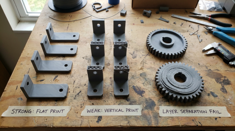
Print Orientation Matters — A Lot
This is the single most important factor. The snap arm must be oriented so that the bending force acts along the layer planes, not across them. If layers are perpendicular to the bending direction, the snap will delaminate and break on the first use.
For a typical cantilever snap on a box lid: print the lid flat on the bed with the snaps extending vertically downward. This way, the snap bends along the XY plane (strong direction) rather than peeling layers apart in Z.
Dimensional Tolerances
FDM printers typically have ±0.2mm dimensional accuracy. For snap fits, this means:
- Clearance fit — add 0.3-0.5mm gap between mating surfaces for easy assembly
- Interference fit — the snap overhang should be 0.5-1.0mm for a satisfying click
- Test print first — always print a small test piece before committing to a full part. Tolerances vary between printers and even between filament brands.
Cantilever Beam Dimensions
The snap arm needs to be long enough to flex without exceeding the material’s strain limit. General rules:
- Length — at least 5x the wall thickness. Longer beams flex more easily and distribute stress better.
- Thickness — 1.5-2.5mm for most applications. Thinner is more flexible but weaker.
- Width — at least 5mm for structural integrity. Wider beams resist twisting.
- Overhang/hook — 0.5-1.0mm deep for a secure connection. Deeper hooks require more deflection force.
- Entry angle — 30-45° on the insertion side for easy assembly. The retention side can be 90° (permanent) or 30-45° (removable).
Designing Your First Snap Fit
Simple Box Lid Example
Let’s design a snap fit lid for a 60mm × 40mm box:
- Box walls — 2mm thick, 30mm tall
- Lid — sits on top with a 0.3mm clearance around the perimeter
- Snap arms — two cantilevers on opposite long sides, 15mm long, 2mm thick, 8mm wide
- Hook depth — 0.8mm overhang on each arm
- Ledge — matching groove on the box inner wall, 0.8mm deep, positioned 2mm below the top edge
- Entry chamfer — 45° angle on the bottom of each hook for easy insertion
When you press the lid down, the snap arms deflect inward, slide past the ledge, and spring back to lock. To remove, squeeze the lid to deflect the arms inward again and pull up.
Adding Finger Grips
For removable snap fits, add small tabs or textured areas near the snap points so the user can push the arms inward. Without these, tight snap fits can be nearly impossible to open — especially in PLA.
Common Failure Modes and Fixes
- Snap breaks on first assembly — arm is too short or thick. Increase length, reduce thickness, or switch to PETG/nylon.
- Snap doesn’t hold — hook is too shallow or clearance is too large. Increase overhang to 1.0mm and reduce clearance.
- Snap works once then loosens — material fatigue. PLA does this. Switch to PETG or reduce the deflection distance.
- Layer delamination — wrong print orientation. Rotate the part so bending happens along layers, not across them.
- Fits on one printer but not another — calibration differences. Use a test piece to determine your specific printer’s tolerance offset.
Advanced Tips
Living Hinges
Combine a snap fit with a living hinge to create flip-open lids. Print a thin strip (0.4-0.6mm, single wall) connecting the lid to the box. PETG and nylon work best — PLA living hinges crack within a few cycles.
Multi-Part Assemblies
For larger projects, design a system of snap fit modules. Use dovetail-style snaps for linear assemblies or radial snaps for things that connect in a circle. Standardize your snap dimensions so parts are interchangeable.
Print-in-Place Snap Fits
With careful design, you can print snap fit assemblies already connected. This requires 0.3-0.5mm clearance between moving parts and careful bridging over the connection points. It’s tricky but eliminates assembly entirely.
Slicer Settings for Snap Fits
A few slicer tweaks improve snap fit performance:
- Wall count — 4+ walls. Snap arms are usually thin enough to be all walls with no infill, which is ideal for strength.
- Layer height — 0.15-0.2mm. Thinner layers improve surface finish and reduce the staircase effect on angled features.
- Print speed — slow down for snap arm features (30-40mm/s) to improve accuracy.
- Cooling — 100% fan for PLA/PETG snap features. Good cooling means sharper corners and tighter tolerances.
Final Thoughts
Snap fits elevate your 3D printing from simple static objects to functional mechanical parts. Start with the simple cantilever design in PETG, print test pieces to dial in your tolerances, and always think about print orientation. Once you’ve got the basics down, you’ll find yourself designing snap fit connections into everything — because screws are overrated.