How to Set Up ADXL345 for Input Shaping on Your 3D Printer (Complete Guide)
What Is Input Shaping and Why Does It Matter?
If you’ve ever pushed your 3D printer past 80 mm/s and noticed ugly ripples on flat surfaces, you’ve met ringing — also called ghosting. It’s caused by vibrations that travel through your printer’s frame every time the printhead changes direction. The faster you print, the worse it gets.
Input shaping is firmware-level vibration compensation. By measuring your printer’s exact resonant frequencies with an accelerometer, the firmware can cancel those vibrations before they reach the print. The result? Clean surfaces at speeds you’d never attempt otherwise.
The ADXL345 is a tiny, inexpensive accelerometer that plugs into a Raspberry Pi (or similar SBC) running Klipper firmware. It costs under $5, installs in minutes, and unlocks the full potential of your machine. Here’s the complete setup guide.
What You’ll Need
Before you start, gather these components:
- ADXL345 accelerometer module — available on Amazon or AliExpress for $3–$8. The GY-291 breakout board is the most common version.
- Raspberry Pi (3B+, 4, or Zero 2W) running Klipper with Moonraker and a frontend like Mainsail or Fluidd.
- Jumper wires — 5 female-to-female Dupont wires, about 20 cm long.
- Mounting hardware — a small zip tie, double-sided tape, or a 3D-printed mount for your specific printhead.
- SSH access to your Raspberry Pi.
Step 1: Wire the ADXL345 to Your Raspberry Pi
The ADXL345 communicates over SPI (Serial Peripheral Interface). Here’s the pinout you need:
| ADXL345 Pin | Raspberry Pi Pin | GPIO |
|---|---|---|
| VCC | Pin 1 | 3.3V |
| GND | Pin 6 | Ground |
| CS | Pin 24 | GPIO 8 (CE0) |
| SDO | Pin 21 | GPIO 9 (MISO) |
| SDA | Pin 19 | GPIO 10 (MOSI) |
| SCL | Pin 23 | GPIO 11 (SCLK) |
Double-check every connection before powering on. A wrong wire won’t fry anything, but SPI is picky about pin assignments. If you’re using a Pi Zero 2W, the pinout is identical — just smaller.
Step 2: Install the Linux SPI Driver
SSH into your Raspberry Pi and run:
sudo apt update
sudo apt install python3-numpy python3-matplotlib libatlas-base-dev
~/klippy-env/bin/pip install -v numpy
Then enable SPI in your Klipper configuration. Open your printer.cfg and add:
[mcu rpi]
serial: /tmp/klipper_host_mcu

[adxl345]
cs_pin: rpi:None

[resonance_tester]
accel_chip: adxl345
probe_points: 150, 150, 20
Set the probe_points to the center of your build plate. For a 300×300 bed, use 150, 150, 20. For a 220×220 bed, use 110, 110, 20.
Restart Klipper after saving the config.
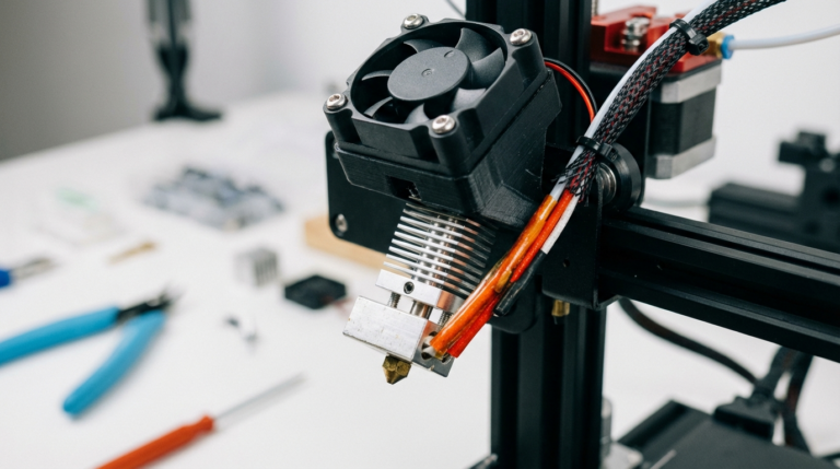
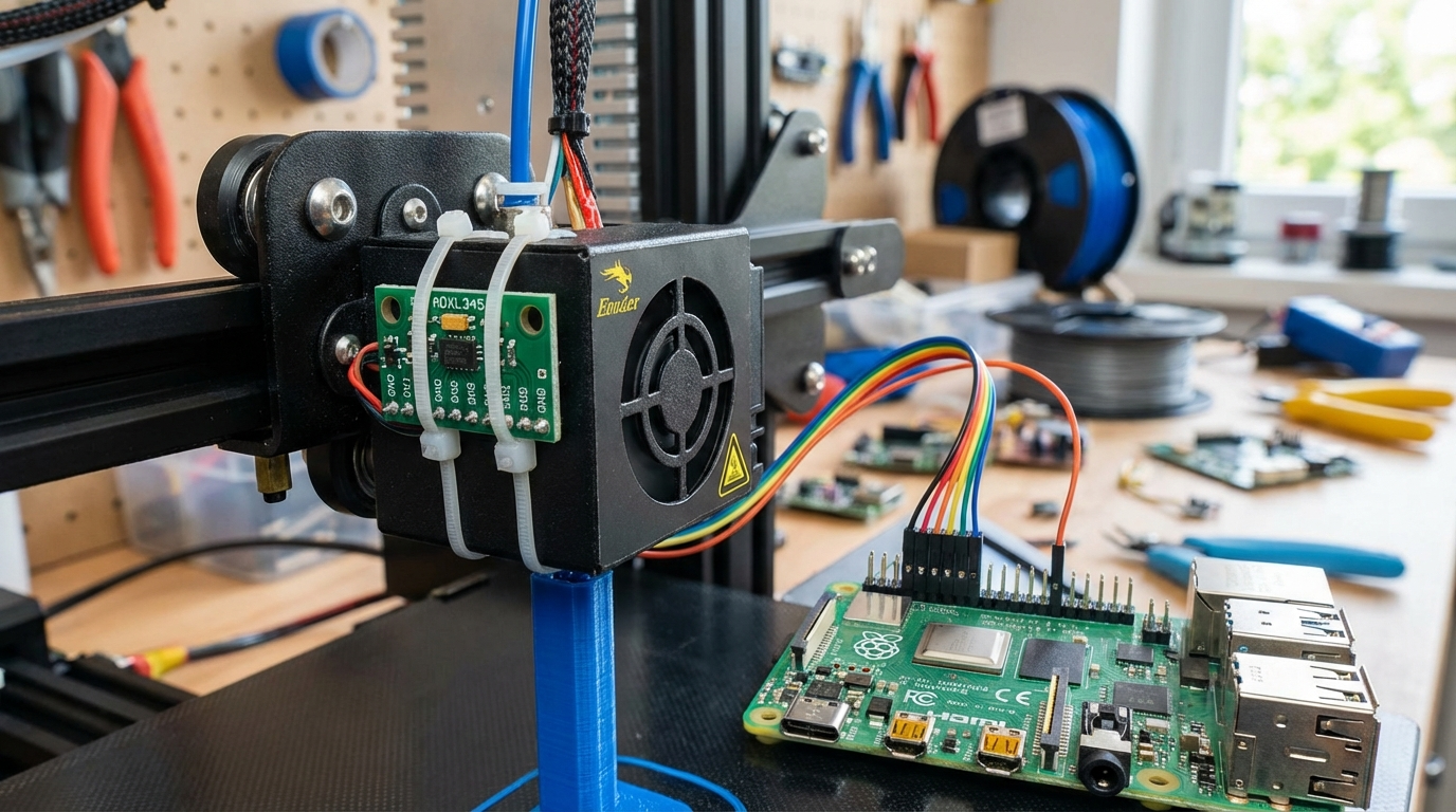
Step 3: Mount the Accelerometer
This is where precision matters. The ADXL345 must be rigidly attached to your printhead — not dangling on wires, not taped to the bed. Any flex between the sensor and the nozzle will give you garbage data.
Options for mounting:
- 3D-printed mount: Search Printables or Thingiverse for your specific printer model + “ADXL345 mount.” This is the cleanest option.
- Double-sided tape + zip tie: Works fine for a quick test. Stick the sensor flat against the printhead carriage and secure with a zip tie.
- M3 screws: Some printhead designs have spare screw holes. If yours does, this is the most rigid option.
The sensor orientation matters too. The chip should be oriented so the X axis aligns with your printer’s X axis. If it’s rotated 90°, you’ll still get valid data — you’ll just need to swap the axis assignments in your config.
Step 4: Verify the Connection
Before running the resonance test, confirm the accelerometer is communicating. In your Klipper console (Mainsail or Fluidd), type:
ACCELEROMETER_QUERYYou should see output like:
Recv: // adxl345 values (x, y, z): -245.123, 45.678, 9812.456If you get an error about SPI communication, double-check your wiring and make sure the klipper_mcu service is running on the Pi:
sudo systemctl status klipper-mcuStep 5: Run the Resonance Test
Now for the exciting part. Home your printer, move the printhead to the center, and run:
TEST_RESONANCES AXIS=X
TEST_RESONANCES AXIS=Y
Each test takes about 60 seconds. The printer will vibrate at increasing frequencies while the accelerometer records the response. You’ll hear a rising whine — that’s normal.
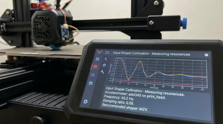
After both tests complete, generate the frequency response graphs:
~/klipper/scripts/calibrate_shaper.py /tmp/resonances_x_*.csv -o /tmp/shaper_calibrate_x.png
~/klipper/scripts/calibrate_shaper.py /tmp/resonances_y_*.csv -o /tmp/shaper_calibrate_y.png
The script outputs recommended shaper types and frequencies for each axis. Typical output looks like:
Recommended shaper is mzv @ 45.6 Hz
Remaining vibrations: 3.2%
Smoothing: 0.078
Step 6: Apply Input Shaper Settings
Add the recommended values to your printer.cfg:
[input_shaper]
shaper_freq_x: 45.6
shaper_type_x: mzv
shaper_freq_y: 38.2
shaper_type_y: mzv
There are several shaper types — MZV is generally the best balance between vibration reduction and acceptable smoothing. EI allows higher speeds but smooths fine details more. ZV is the lightest option with least smoothing but also least vibration reduction.
For most printers, stick with whatever the calibration script recommends. It analyzes your specific resonance profile and picks the optimal algorithm.
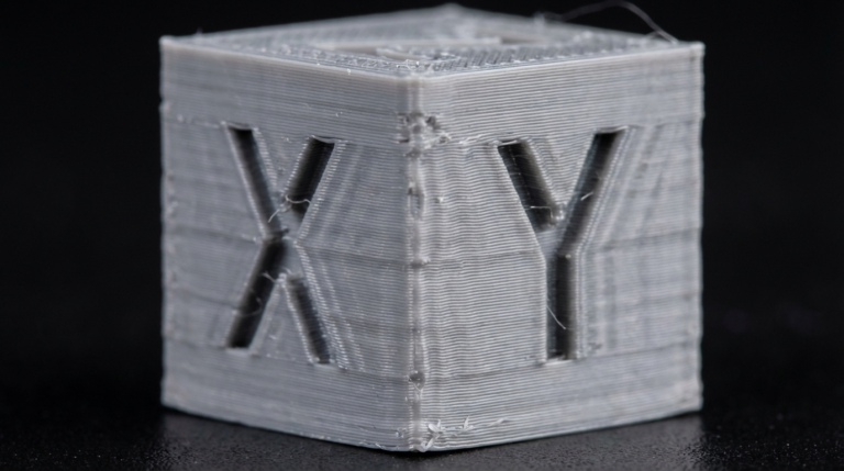
Step 7: Test Print and Fine-Tune
Print a test cube or a ringing test model at 100+ mm/s. Compare it to a cube printed before input shaping. The difference should be dramatic — clean walls with no ghosting artifacts.
If you still see faint ringing, try these adjustments:
- Re-run the test with a tighter mount. Even slight flex corrupts measurements.
- Switch to the EI shaper type for more aggressive compensation.
- Check that your belts are properly tensioned — loose belts shift resonant frequencies unpredictably.
- Make sure the accelerometer wasn’t touching any wires during the test.
Common Problems and Solutions
“ADC out of range” error: This usually means a wiring issue. Check that VCC is connected to 3.3V, not 5V. The ADXL345 is a 3.3V device.
Noisy graphs with no clear peaks: Your mount isn’t rigid enough. The sensor is picking up its own vibrations instead of the printer’s. Tighten the mounting or switch to a screw-on solution.
Different results each time you test: Make sure the printer is on a stable surface and the belts haven’t changed tension between tests. Temperature can also affect belt tension slightly.
High remaining vibration percentage (>10%): Your printer may have multiple resonant frequencies close together. Try the 2HUMP_EI or 3HUMP_EI shapers, which handle complex resonance profiles better.
Should You Leave the ADXL345 Permanently Mounted?
You can, but most people don’t. Once you’ve dialed in your input shaper settings, the accelerometer’s job is done. Remove it to reduce printhead weight (even a few grams matter at high speeds). Re-mount it only when you make mechanical changes — new belts, different hotend, frame modifications — that might shift your resonant frequencies.
Some dedicated Klipper users wire a permanent ADXL345 and run SHAPER_CALIBRATE automatically before every print. That’s overkill for most setups, but if you’re chasing perfection at 200+ mm/s, it ensures your compensation stays current.
Final Thoughts
Setting up an ADXL345 for input shaping is one of the highest-impact upgrades you can do on a Klipper-based 3D printer. For under $5 and 30 minutes of work, you’ll eliminate ghosting artifacts and print faster with better quality. The hardest part is wiring — and even that’s just five jumper wires.
If you’ve been avoiding high-speed printing because of ringing, this is the fix. Get the sensor, run the test, apply the settings, and start printing like your machine was meant to.