PETG vs ASA for Car Parts Under the Hood: Which Survives the Engine Bay
The engine bay is a torture test
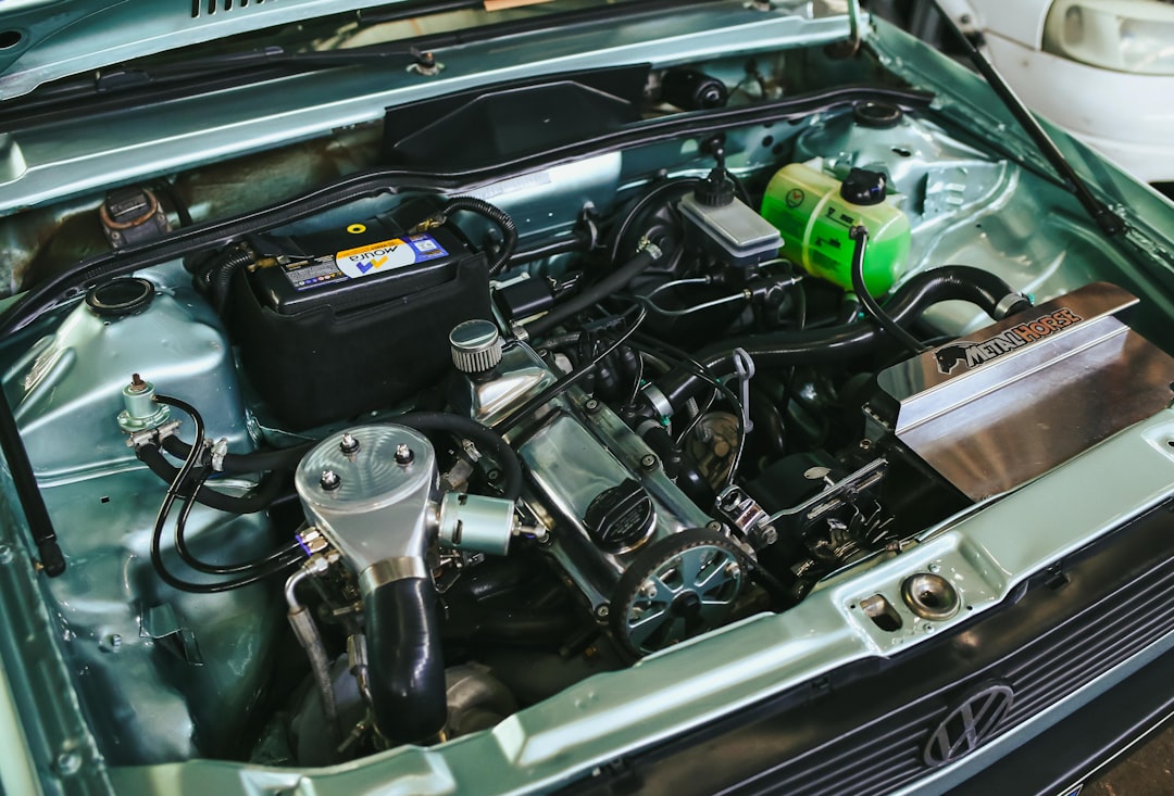
Under-hood automotive parts get a combination of conditions almost no other consumer environment produces simultaneously. Sustained operating temperatures sit at 70-90°C in air, with hotspots near the exhaust manifold and turbocharger reaching 130-180°C. Direct sunlight through a hood vent or open hood adds UV. Engine fluids splash routinely — engine oil, coolant, brake fluid, gasoline, washer fluid, transmission fluid. The whole assembly vibrates at engine RPM and shock loads at suspension events. Whatever filament you pick has to handle all of this, and PETG and ASA are the two filaments most home printers can run that come close to surviving it.
So which one wins? The honest answer is that they win in different parts of the engine bay. Neither is a universal under-hood filament. Picking the right one requires knowing the specific zone of the bay your part lives in.
The four under-hood zones
Under-hood real estate is not uniform. For filament selection, divide the bay into four zones by sustained ambient temperature:
- Zone A — front near radiator and intake (45-65°C): air entering the bay, cooled by the radiator fan, exposed to road grit and water but not extreme heat. Examples: intake trim covers, washer fluid bottle brackets, sensor housings on the radiator support.
- Zone B — central bay above engine (65-90°C): the bulk of under-hood space. Engine bay ambient when running. Examples: airbox covers, fuse box brackets, battery hold-downs, ECU mounts, harness retainer clips.
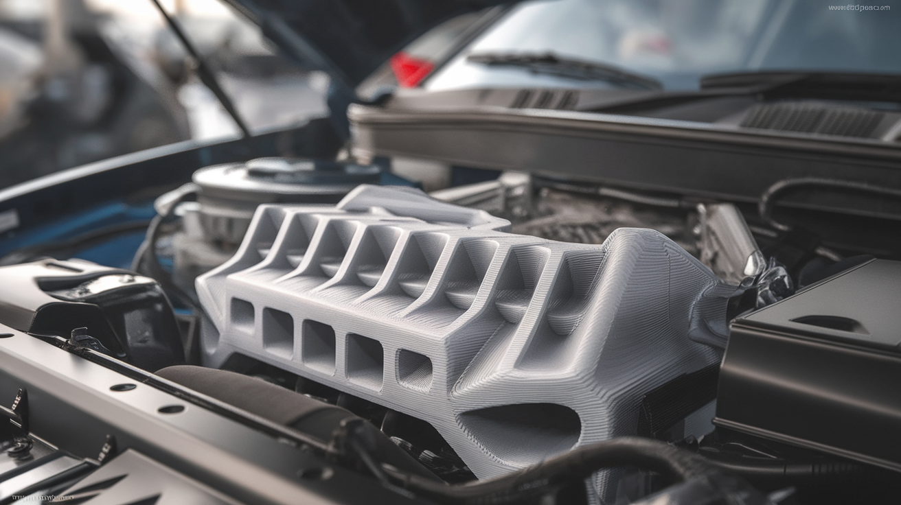
- Zone C — engine-adjacent (90-130°C): bracketry directly bolted to the engine block, valve cover, or intake manifold. Examples: PCV catch can brackets, intake plenum spacers, oil cap retainers.
- Zone D — exhaust-adjacent (130°C+): any part within 4 inches of an exhaust manifold, turbo, or downpipe. Examples: turbo heat shields, exhaust manifold covers. Neither PETG nor ASA belongs here. Use metal or high-temp engineering filaments only.
PETG’s strengths and weaknesses for engine bay use
PETG has a glass transition temperature around 80°C and a continuous service temperature around 65-70°C. In Zone A you can use PETG with confidence — the temperatures are below the softening point and PETG handles the chemical exposure of road grit and washer fluid easily. PETG is also cheaper than ASA, prints with less fuss, and does not require an enclosed printer.
The weakness is heat. By the time you get to Zone B at sustained 80-90°C, PETG starts to creep — the part holds shape on bench inspection but slowly deforms under load. A PETG fuse box bracket may look fine after a year and then quietly sag enough to throw a fault. PETG is also damaged by gasoline and brake fluid. Brief splashes are tolerable; sustained contact is not.
The other PETG weakness is UV. Standard PETG yellows and embrittles in direct sunlight over a year of exposure. Most under-hood parts are not in direct sunlight, so this matters mostly for parts visible through a hood scoop or a vented hood. PETG-CF (carbon fiber filled) is somewhat more UV-stable but the unfilled colored variants are not.
ASA’s strengths and weaknesses for engine bay use
ASA has a glass transition temperature around 100°C and a continuous service temperature around 80-90°C. That extra 20°C of heat tolerance puts it comfortably into Zone B. ASA is also UV-stable, oil-resistant, and not damaged by short exposure to most automotive fluids. This is exactly the property combination that makes it the standard hobbyist choice for visible exterior trim and engine-bay parts that see real heat.
The weaknesses are mechanical and process-based. ASA is more brittle than PETG at room temperature, especially in the layer adhesion direction. A PETG bracket bent past its yield point usually deforms; an ASA bracket of similar geometry may snap. ASA also requires an enclosed printer with active heating to print without layer cracks — open-frame Ender 3 owners can technically print ASA, but layer adhesion will be unreliable and the parts will fail at the layer lines.
ASA is also more expensive (typically 1.4-1.8x PETG per kilogram), and the printing process emits more aggressive fumes than PETG, which means you need ventilation in your print space.
Zone-by-zone recommendation
Putting the two filaments together against the four zones:
- Zone A: PETG is sufficient. Pick ASA only if the part is in direct sunlight where UV stability matters.
- Zone B: ASA is the better choice for sustained service. PETG works for short-term parts (track-day brackets, prototypes) but should not be used for daily-driver parts that will see summer engine bay temps.
- Zone C: Neither is a great choice. ASA can survive briefly (under 110°C) but creeps. Move to polycarbonate, PA-CF, or aluminum for anything in this zone. If you must use ASA, design with very generous safety margins and check the part annually.
- Zone D: Neither. Metal only.
Mechanical failure modes you actually see in the bay
Filament data sheets list properties at 23°C and 50% humidity. The engine bay is not 23°C, and the failure modes you see in service are not the failure modes the data sheet describes.
The most common failure for PETG in the bay is creep deformation. The part visibly maintains its shape for the first month, slowly sags under bolt preload over the next six months, and finally cracks at a stress concentration when the geometry has drifted enough that the load is no longer aligned with the part’s strongest direction. By the time it fails, it does not look like a brittle break — it looks like the part deformed first, then snapped.
The most common failure for ASA in the bay is layer-line cracking from a combination of thermal cycling and vibration. Each engine warmup-cooldown cycle puts the part through a temperature swing, and each swing relaxes residual stresses asymmetrically across layers. A part printed on an unenclosed printer with marginal layer adhesion may survive 50-200 thermal cycles before a crack propagates from a layer line. Engine vibration accelerates this.
The fix for the ASA failure mode is printer environment, not filament choice. ASA printed in a properly heated chamber (40-50°C ambient) with annealing afterwards has dramatically better layer adhesion and survives the bay much longer.
Print settings that matter for under-hood durability
For both PETG and ASA, the settings that move the needle on engine bay survival are wall count, infill geometry, and post-print conditioning.
Use four perimeters minimum on any structural under-hood part. Three is the slicer default, four is the safety margin you want for a part that lives in vibration. The walls do most of the load-bearing for thin-walled brackets; infill mostly handles compression.
For infill, pick gyroid or honeycomb at 30-40%. Avoid grid and rectilinear infills for engine bay parts because they have planes of weakness aligned with the print bed. Gyroid distributes load isotropically, which matters for parts that see vibration from multiple directions.
For PETG, anneal at 70°C for 4-6 hours after printing. This relaxes residual stresses and adds a few degrees of effective service temperature. For ASA, anneal at 95°C for 6-8 hours. Both materials warp slightly during annealing, so design with a few millimeters of clearance on critical fits and assume the annealed part is the dimensionally accurate version.
Coolant, fuel, and oil compatibility
PETG is rated as resistant to brief automotive fluid exposure but is permanently damaged by sustained contact with gasoline, brake fluid, or strong solvents. Engine oil and coolant are tolerable for incidental splashes but not for a part submerged in a fluid path.
ASA is similarly rated. Both filaments will not survive being used as a fluid container — gas tank parts, coolant reservoirs, oil catch can bodies. Use the printed parts as brackets and covers, not as fluid-containing structures, regardless of which filament you pick.
Vibration design tips
Engine vibration is a fatigue load. Stress concentrations that would be fine for a static load become crack initiation sites under cyclic loading. The fixes are geometry-driven and apply equally to PETG and ASA:
- Generous fillets at every internal corner — minimum 3 mm radius, 5 mm preferred.
- Avoid sharp transitions in cross section. Tapered transitions distribute stress better.
- Design bolt holes with at least 2x the bolt diameter of material around them to prevent tear-out under vibration.
- Use rubber isolators where the printed bracket meets the engine, not metal-to-plastic-to-metal contact. The isolator dampens the vibration the part has to absorb.
What the data sheets do not tell you
Manufacturer data sheets list HDT (heat deflection temperature) and tensile strength under controlled lab conditions. The number you actually want for under-hood use does not appear on most data sheets: the long-term creep modulus at 80°C with the part under sustained bolt preload. Filament makers rarely publish this because it requires weeks of testing per data point. The practical workaround is to overbuild your design.
For a part the data sheet says will hold 50 N at 80°C, design assuming it will hold 25 N. For wall thickness the slicer suggests at 1.6 mm, use 2.4 mm. The doubled safety factor compensates for creep, fatigue, and the inevitable manufacturing variance between filament batches. Engineering plastics are forgiving when you treat them like the structural materials they are; they fail unpredictably when designed at the data sheet’s listed limits.
The honest summary
For a typical under-hood project — a fuse box bracket, an air intake trim cover, an ECU mount — print it in ASA if you have an enclosed printer and the part will see sustained engine bay temperature. Print it in PETG if you have an open-frame printer and the part lives near the front of the bay where it stays cool. For anything within four inches of an exhaust component, neither filament is appropriate; switch to metal. The wrong filament in the wrong zone fails in months. The right filament in the right zone lasts the lifetime of the car.