Carbon Fiber Filament Comparison 2026: CF-PLA vs CF-PETG vs CF-Nylon Strength and Z Adhesion
What Carbon Fiber Filament Actually Is in 2026
“Carbon fiber filament” describes a family of composites in which short chopped carbon strands are mixed into a base polymer at fill rates between 10 and 25 percent by weight. The fibres are typically 100 to 200 micrometres long — too short to span a layer, but long enough to dominate the in-layer mechanical properties of the printed part. This is the source of every carbon fiber printing trade-off in the literature: parts get stiffer and more dimensionally stable along the print plane, and softer relative to virgin material across layer boundaries.
The three common base polymers in 2026 are PLA, PETG, and the nylon family (PA6, PA12, and increasingly PA-CF blends like CF-PA6-GF). Each base polymer brings its own properties to the composite, and the resulting filaments are not interchangeable. Picking the wrong one for the application is the dominant failure mode in functional carbon fiber printing — far more common than any settings issue.
CF-PLA: Stiffness Without the Engineering Cost
CF-PLA exists for one reason: it is the easiest carbon fiber filament to print successfully. The base polymer keeps the same low-temperature, no-chamber, no-enclosure printing behaviour PLA is known for. The added carbon fibres raise the apparent stiffness — visually obvious in printed parts with thin walls or long unsupported spans — and reduce the gloss and translucency that mark virgin PLA. Z-axis adhesion stays roughly equivalent to base PLA, which is to say: acceptable for non-load-bearing prints, marginal for structural use.
Where CF-PLA succeeds is in display models, lightweight tool housings, drone fairings that will not see meaningful mechanical load, and parts that need to look like carbon-fibre composite for aesthetic reasons. Where it fails is anywhere stress is applied across the layer boundaries. A CF-PLA part loaded perpendicular to the print plane delaminates at almost the same load as a virgin PLA part — the fibres do not bridge the gap. Operators who try to substitute CF-PLA for engineering use cases discover this on the first real load test.
CF-PETG: The Middle Ground That Actually Works
CF-PETG is the underappreciated workhorse of the 2026 carbon fiber composite space. It prints almost as easily as CF-PLA — 240-250 degree nozzle, 75-85 degree bed, no enclosure required — and inherits PETG’s superior layer adhesion. The result is a composite that retains a useful fraction of its in-plane stiffness when loaded across the print plane, which is where CF-PLA falls apart.
For mechanical brackets, jigs, fixtures, and structural housings that will see temperatures up to 70 degrees and modest mechanical stress, CF-PETG is the default recommendation in 2026. It is not as dimensionally stable as nylon composites at temperature, and it does not match nylon’s impact resistance, but it covers the practical middle of the engineering envelope at a fraction of the print difficulty.
The catch with CF-PETG is nozzle wear. PETG is already mildly abrasive; add 20 percent chopped carbon and a brass nozzle is good for roughly 200 to 300 print hours before the orifice diameter has grown enough to push flow calibration out of spec. Hardened steel or tungsten carbide nozzles are not optional for any serious CF-PETG run.
CF-Nylon: The Engineering Choice
CF-Nylon — most commonly CF-PA6 or CF-PA12 in 2026 — is what carbon-fibre composite printing is for. The base polymer brings high impact resistance, dimensional stability up to 130 degrees, chemical resistance to most solvents, and excellent fatigue performance. The chopped carbon raises in-plane stiffness, reduces moisture-driven dimensional drift, and damps the vibration that nylon-only parts can show in dynamic applications.
The cost is real. CF-Nylon needs a hotend temperature of 280 to 300 degrees, a heated chamber at 60 to 80 degrees ambient, an enclosed printer with high heat tolerance on the electronics, and dry filament — bone dry, not “we stored it in a Ziploc with a desiccant pack” dry. Wet CF-Nylon prints with audible popping, surface bubbles, and an immediate hit on both strength and stiffness. The 2026 working assumption is to keep CF-Nylon in a 50-degree dryer during the print itself, fed by a PTFE tube to the extruder.
For drone arms, RC vehicle suspension, robotics gripper fingers, and any prosthetic or jig that will see repeated load cycles, CF-Nylon outperforms CF-PETG by a wide margin. For everything else, the engineering effort to print it correctly does not pay back.
Z-Axis Adhesion: The Three-Way Result
The most useful way to compare these three composites is to measure tensile strength along the print plane (XY) and across layer boundaries (Z), and to look at the ratio. A typical 2026 result from a tuned direct-drive printer with hardened nozzle:
- CF-PLA: XY ~ 55 MPa, Z ~ 18 MPa (Z/XY ratio 0.33). Brittle delamination failure.
- CF-PETG: XY ~ 50 MPa, Z ~ 32 MPa (Z/XY ratio 0.64). Ductile failure, fibres pulling clean.
- CF-Nylon (PA6-CF): XY ~ 70 MPa, Z ~ 48 MPa (Z/XY ratio 0.69). Ductile failure, post-yield deformation.
The ratio matters more than the absolute number. A part that has been oriented to load along XY will benefit from the high XY number; one that takes load in any direction needs the high ratio. CF-Nylon wins both, CF-PETG covers the middle, and CF-PLA is appropriate only when the part will never see Z-direction load.
Settings, Nozzles, and Practical Setup
Across all three composites, three setup decisions repeat. First: hardened steel or tungsten carbide nozzle is required. Brass nozzles wear within 200 hours and the resulting orifice drift kills calibration silently. Second: print at the higher end of each composite’s recommended nozzle temperature — fibre-matrix bonding improves above the polymer’s standard print range. Third: dry the filament. All three composites absorb moisture faster than their virgin counterparts because the fibre-polymer interface acts as a wick.
Flow calibration should be done on the actual composite, not extrapolated from virgin filament settings. The chopped fibres displace some volume in the melt zone and the effective extrusion multiplier for CF variants is typically 2 to 5 percent lower than for their base resins.
Picking One for Your Part
The 2026 selection logic is simple. Cosmetic part, no real load: CF-PLA. Mechanical bracket, jig, or housing under 70 degrees, modest stress: CF-PETG. Engineering part that will see impact, fatigue, temperature above 80 degrees, or chemical exposure: CF-Nylon. Most makers underestimate how often CF-PETG is the right answer — it is not the prestige choice in the literature, but it is the one that ships parts.
Drying: How Wet Composite Filament Loses Its Properties
All three composites lose mechanical performance when printed wet, but the failure mode differs by base polymer. Wet CF-PLA shows surface bubbles and a small loss of in-plane strength — usually 5 to 10 percent on tensile tests. Wet CF-PETG bubbles more visibly, loses layer adhesion noticeably, and prints with audible popping that can be mistaken for nozzle clog. Wet CF-Nylon is the disaster case: tensile strength drops by 30 to 50 percent, layer adhesion fails outright in many orientations, and the printed part can crack hours after coming off the bed as residual moisture migrates.
The required drying schedule scales with base polymer. CF-PLA needs four hours at 45 degrees if a spool has been exposed for more than a week. CF-PETG needs six hours at 65 degrees on the same timeline. CF-Nylon needs twelve hours at 80 degrees and then continuous dry storage during printing — a heated dryer feeding the extruder directly via PTFE tube is the standard 2026 setup for any serious CF-Nylon work. Operators who skip the in-print drying step for nylon composites discover the moisture problem one print at a time across days, blaming the filament brand instead of the storage.
Print Orientation: How to Use the Z-Strength Ratio
The XY/Z strength ratios above are not just numbers — they are direct guidance for part orientation. A bracket that takes its primary load along one axis should be oriented so that axis runs along XY in the print. A pulley or rotating part that takes load circumferentially should be sliced so the radial direction is also XY, not Z. The Z direction is reserved for the part’s least-loaded axis when possible. For CF-PLA, this orientation rule is rigid — load across Z fails first. For CF-PETG and CF-Nylon, the rule still applies but the penalty for breaking it is smaller because Z-strength is higher to start with.
Operators who design parts in CAD without thinking about print orientation routinely end up rotating their CF print 90 degrees during slicing to handle Z-strength concerns, only to discover that the new orientation needs more supports and longer print time. Designing for orientation first — and slicing second — is the workflow that produces strong CF parts on the first print rather than the third.
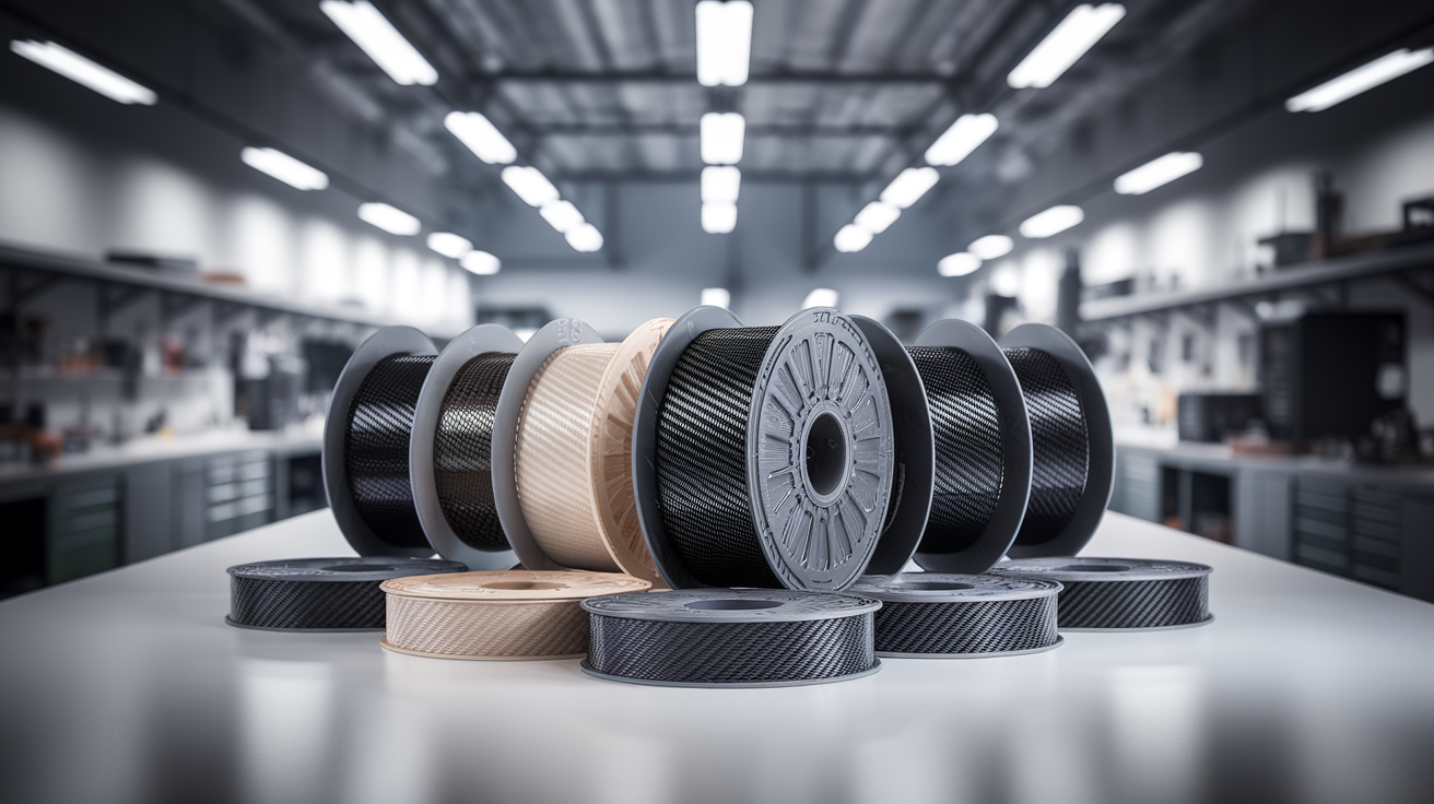
Price and Availability in 2026
Per-kilogram pricing as of mid-2026 has stabilised after the supply disruptions of the early 2020s. CF-PLA sits in the 35 to 50 US dollar range from quality vendors, with no-name brands as low as 25 dollars at a meaningful quality penalty. CF-PETG runs 45 to 65 dollars per kilogram, slightly more than CF-PLA because of the higher base resin cost. CF-Nylon spans the widest range — 70 dollars per kilogram for entry-level CF-PA6 from established Asian suppliers, up to 180 dollars per kilogram for branded engineering-grade CF-PA12 from Western chemical companies. The price spread on nylon composites tracks fibre quality, fibre orientation control during compounding, and moisture-control during packaging more than it tracks brand premium alone, and the cheaper end of the range is genuinely usable for non-critical applications.